EasyManua.ls Logo

CEMONT PUMA S 1600 User Manual

CEMONT PUMA S 1600
76 pages
To Next Page IconTo Next Page
Page #1 background imageLoading...
Page #1 background image
EN Safety instruction for use and maintenance - Do not destroy this manual
FR Instruction de securite d’emploi et d’entretien - Conserver ce livret d’instructions
ES Instrucciones de seguridad, empleo y mantenimiento - Conservar el presente manual
IT Istruzioni per la sicurezza nell’uso e per la manutenzione - Conservare il presente libretto
DE Betriebs-Wartungs und Sicherheitsanleitung - Das vorliegende Handbuch gut aufbewahren
PT Instrucões de segurança de utilização e de manutenção - Conserve este manual
SV Instruktioner för säkerhet, använding och underåll - Spar denna handledning
NL Veiligheidsinstructies voor gebruik en onderhoud - Bewaar deze handleiding
RO Instructiuni privind siguranta in exploatare si intretinerea - Pastrati acest manual
SK Bezpečnostné pokyny pri používaní a pri údržbe - Odložte si tento návod na použitie
CS Bezpečnostní pokyny pro používání a údržbu - Návod na používání si uchovejte
HU Használati és karbantartási biztonsági utasítások - Kerjük őrizze meg ezt a hasznsnalati utasítást
PL Instrukcje bezpieczeństwa podczas obsługi i konserwacji - Zachować niniejszą instrukcję na przyszłość
EL ΟΔΗΓΙΕΣ ΑΣΦΑΛΕΙΑΣ ΚΑΤΑ ΤΗ ΧΡΗΣΗ ΚΑΙ ΤΗ ΣΥΝΤΗΡΗΣΗ – ΦΥΛΑΞΤΕ ΤΟ ΠΑΡΟΝ ΕΓΧΕΙΡΙΔΙΟ
RU РУКОВОДСТВО ПО БЕЗОПАСНОЙ ЭКСПЛУАТАЦИИ И ТЕХНИЧЕСКОМУ ОБСЛУЖИВАНИЮ
www.airliquidewelding.com
Air Liquide Welding - 13, rue d’Epluches - BP 70024 Saint-Ouen L’Aumône
Cat. Nr.:
Rev.:
Date:
PUMA S 1400 / S1600 / S1700G
800035044
02
11. 02. 2008

Table of Contents

Question and Answer IconNeed help?

Do you have a question about the CEMONT PUMA S 1600 and is the answer not in the manual?

CEMONT PUMA S 1600 Specifications

General IconGeneral
Input Voltage230 V
Welding Current Range20 - 160 A
Electrode Diameter1.6 - 4.0 mm
Output Current Range20 - 160 A
No-load Voltage60 V
Protection ClassH
Duty Cycle60% at 160 A
Power SupplySingle Phase

Summary

Technical Description

Product Overview

General overview of the welding generator system, its technology, and applications.

Technical Specifications

Detailed technical specifications for 130A and 150A models, including supply, current, and dimensions.

Duty Cycle and Overheating

Explanation of duty cycle, overheating indicators, and procedures to follow if the unit overheats.

Volt-Ampere Curves

Explanation of how volt-ampere curves represent the welding power source's output capabilities.

Installation

Connecting to Mains Electricity

Safe procedures for connecting the welding generator to the main electricity supply.

Handling and Transportation

Safety guidelines and procedures for safely lifting, handling, and transporting the welding power source.

Selecting a Location

Criteria for choosing a safe and suitable operating location, considering ventilation and access.

Stick Welding Connections

Steps for connecting equipment for stick welding, including electrode and earth clamp connections.

TIG Welding Connections

Steps for connecting equipment for TIG welding, including torch, earth, and gas hose connections.

Controls and Functions

Front Panel Overview

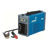
Identification and explanation of controls, indicators, and connection terminals located on the front panel.

Maintenance

Scheduled Maintenance Tasks

Routine maintenance tasks recommended every three and six months to ensure optimal performance and longevity.

Spare Parts

Declaration of Conformity

Related product manuals