Pg. 9V06232023
A. Install Guide Rods (#7) into holes on bottom Frame using M10 x 80 Allen Bolt (#18) and Ø 10 Spring
Washers (#25). Tighten.
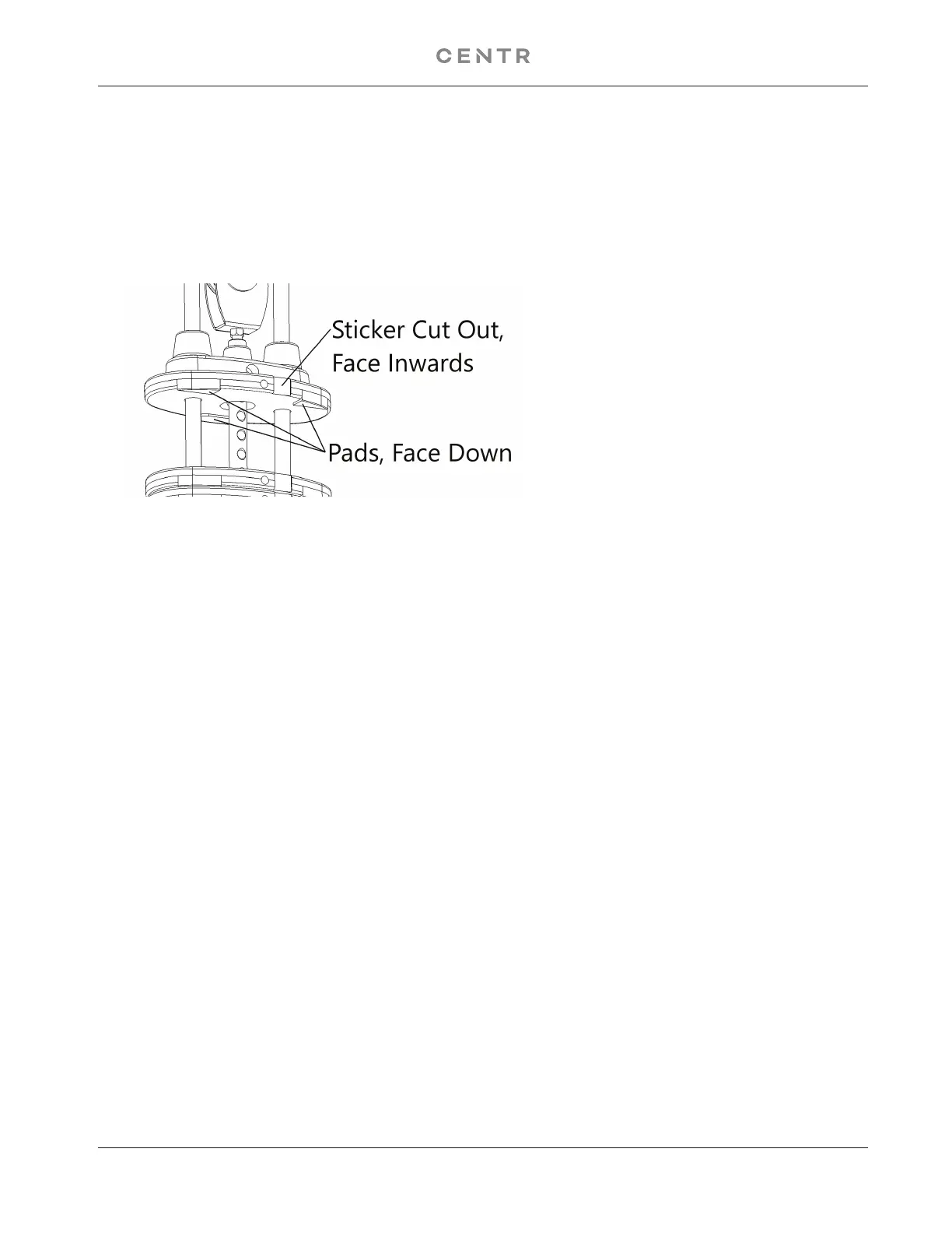
B. Install Rubber Bumpers (#16) on each Guide Rod (#7). Slide fifteen 10lb Weight Plates (#10) from the
top of Guide Rods (#7) down to the Rubber Bumpers (#16). Make sure the weight sticker cut out is
facing the inside of the machine and the pads of the weight face down. See example below:
C. Remove the two M10 x 20 Allen Bolts (#21), Ø 10 Spring Washers (#23), and Ø 10 Washers (#25)
which were pre-assembled in the factory to hold the Guide Rod Bracket (#6). Slide the Selector Stem
Assembly (#8) onto the Guide Rods (#7). Install the weight stack Pulley (#33) with the cable wrapped
between the pulley and the U shaped bracket (#31). Then insert the Cam Bolt (#32) and secure with a
Ø 10 Washer (#25), and a M10 Aircraft Nut (#24).
D. Hold the Selector Stem Assembly (#8) above the weight stack to make it easier to install Guide Rod
Bracket (#6) on Guide Rods (#7).
E. Once the Guide Rod Bracket (#6) is installed onto the Guide Rods (#7), Push the Guide Rod Bracket
back into the upright.
F. Secure the Bracket back to the upright frame with the two M10 x 21 Allen Bolts (#21), Ø 10 lock Washers
(#23), Ø 10mm Washers (#25).
G. Lower the Selector Stem down onto the top of the weight stack.
H. Check all the cables to make sure they are on track on the pulleys.
I. Peel off the weight stack number label from the Resistance Label Set (#26) and attach to the plates,
starting with number one on the selector stem weight.
J. Insert the Weight Selector Pin (#9) into the weight stack.
K. Lubricate the Guide Rods with super lube or lube provided in Hardware Pack.
L. If Needed, Adjust the cable tension by loosening and rotating the Cam Bolt (#32) until the Selector Steam
Assembly (#8) starts lifting slightly from the weight stack. Tighten the nut of the cam bolt to lock it’s position.
M. above to install the other set of weight plates to the Left Station. (#2)
 Loading...