Do you have a question about the Central Pneumatic 1118 and is the answer not in the manual?
Ensure clean, lit, dry work area. Keep children away. Dress properly, use eye/ear protection.
Use right tool, store idle equipment, avoid overreaching. Maintain tools and disconnect power.
Do not exceed 160 PSI, avoid unintentional starts, stay alert. Use only as intended.
Check for damaged parts before use. Use only identical replacement parts.
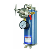
Check all parts are included against the photo and parts list. Contact for missing/broken items.
Thread Nipple (1B) into Plug (1A) using Teflon tape or pipe dope.
Thread Air Regulator (3B) onto Nipple (1B) and Air Valve (5B) into Regulator Assembly.
Thread Regulator Handle (1C) into the Air Regulator (3B) until tight.
Connect compressor output hose to Air Inlet (7B) and secure tightly. Ensure compressor is off.
Connect output hose to Quick Coupler, screw into Air Valve (5B), and connect to air tool.
Turn on compressor, check leaks, set desired pressure using Adjusting Screw (1C).
Drain accumulated moisture daily. Periodically disassemble, clean filter, or replace filter element.
Diagram and list of components including Nipple, Elbow, Regulator, Valve, Gauge, Inlet.
Diagram and list of components including Plug, Filter, Housing, Handle, and Filters.
Manufacturer provides parts diagram as reference only; repairs by qualified technicians.
Warranty covers defects in materials/workmanship for one year; excludes misuse and alterations.
| Brand | Central Pneumatic |
|---|---|
| Model | 1118 |
| Category | Air Cleaner |
| Language | English |