10.3. Conguration
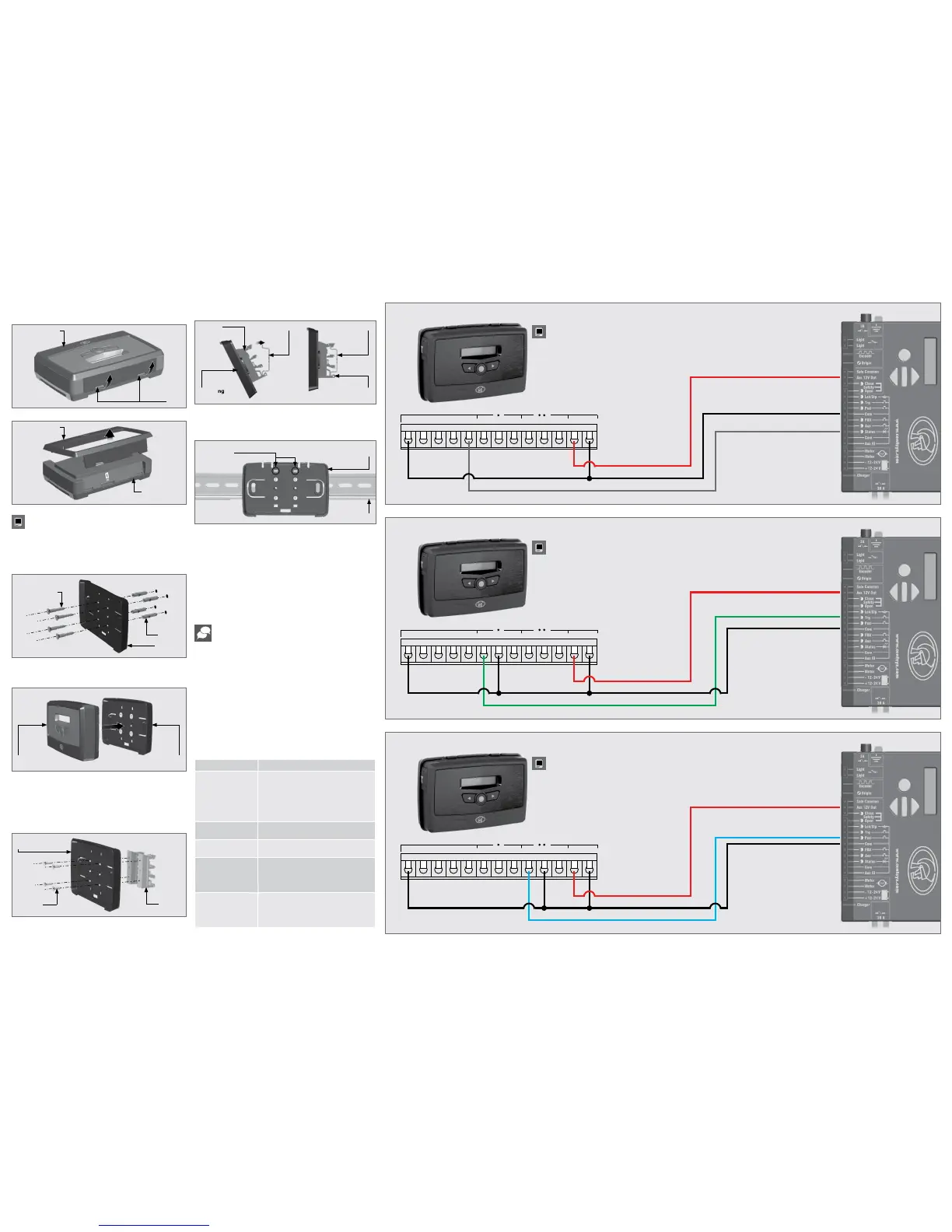
10.4. Wiring Diagrams
10.3.1. G-WEB
10.3.2. SMS Commands
1. Complete the wiring of the unit as per Section 8 and 10.4 of this
document.
2. Power up the device and verify that the device connects to the G-WEB
platform by referring to the LCD home screen.
3. Navigate your Internet browser to http://www.gweb.co.za
(or www.g-web.com.au for Australia and New Zealand) and login to your
existing prole or, alternatively, register a new prole.
4. On the My Devices page, select Add New G-ULTRA Device and follow the
onscreen instructions to associate the device to your prole.
5. Congure the device with the desired settings using your online portal.
All features – both basic and advanced – can be easily, and remotely,
congured via the G-WEB online interface. By simply logging into G-WEB
using any Internet-enabled device, one can add and delete devices, specify
text for input and output notications and activations, modify device
characteristics and a plethora of other features, all from the comfort of one’s
home or oce. G-WEB can be accessed by navigating to http://www.gweb.
co.za (or www.g-web.com.au for Australia and New Zealand). Note that it
will be necessary to register if you have not previously done so.
The table below lists the optional basic SMS commands available on the
G-ULTRA. All basic and advanced congurations can be done via the G-WEB
online portal.
Quick Add:
To instantly associate a device to your online prole, scan
the QR code using your mobile phone and any universal QR
scanner mobile application.
SMS Command
Description
P.XXXX
1
.STATUS
Device Status Request to which the device
will respond with the following information:
• IMEI
• Supply Voltage
• Signal Strength
• Device date & time
P.XXXX.AP.Number
Add New Phone Number which will by
default pulse Relay 1 by missed call
P.XXXX.DP.Number
Delete a specic access number from the
G-ULTRA’s memory
P.XXXX.OUT.Y.ON
Switch output ON where Y is the
corresponding output number
IO1 Y=1, IO2 Y=2, IO3 Y=3, IO4 Y=4,
RELAY1 Y=5, RELAY2 Y=6
P.XXXX.OUT.Y.OFF
Switch output OFF where Y is the
corresponding output number
IO1 Y=1, IO2 Y=2, IO3 Y=3, IO4 Y=4,
RELAY1 Y=5, RELAY2 Y=6
1. XXXX = Device Default Password
TABLE 4
10.2. Installation
10.2.1. Wall-mounting
10.2.2. DIN Rail-mounting
FIGURE 5
FIGURE 6
FIGURE 7
FIGURE 8
FIGURE 9
FIGURE 10
FIGURE 11
FIGURE 12
FIGURE 13
Reverse the procedure under Section 10.1 to re-assemble the
G-ULTRA.
G-ULTRA Fascia
Main G-ULTRA
Unit
The Mounting Plate is used to mount the G-ULTRA device to a wall. Use four
screws with wall anchors(not supplied) to secure Mounting Plate.
Clip the G-ULTRA main unit into the Mounting plate after it has been
secured to the wall; a ‘click’ will be heard if done correctly.
Should the G-ULTRA need to be mounted onto a DIN-rail, a DIN-rail
mounting kit is available. Ask at Centurion Systems (Pty) Ltd for more
information.
Secure the DIN-rail clips to the back of the mounting plate using four (4)
screws.
Position the bottom of the DIN-rail clips onto the rail, and clip the top end
into position(A). A ‘click’ will be heard if it has been done correctly(B). Clip
the G-ULTRA main unit into the Mounting plate after it has been secured to
the wall; another ‘click’ will be heard if done correctly.
To remove the unit from the DIN-rail, remove the G-ULTRA main unit from the
mounting plate as described in Section 10.1. Insert a small at screwdriver
into the hole(s) shown in Figure 10, and gently pry the clips from the rail.
Mounting
Plate
Mounting
Plate
Mounting
Plate
Mounting
Plate
Mounting
Screws
G-ULTRA
Main Unit
Mounting
screws
(Not Supplied)
Wall
anchors
DIN-rail
Clips
The fascia can be removed by inserting the tips of one’s ngers into the
slots (as shown in Figures 4 and 5), and pulling outward and upward.
The fascia should pop o without eort.
10.1.2. Removing the Fascia
FIGURE 4
G-ULTRA Fascia
Slots
• I/O Status
• Firmware Version
• Relay Status
‘click’
BA
DIN-rail
Clip
Holes for
Screwdriver
Mounting
Plate
DIN Rail
DIN rail
Clip
DIN-rail DIN-rail
Gate Status Monitoring
GND IO4 NOIO1 NO COMIO2 COM NCIO3 NC + VDC -
G-ULTRA
D-Series
Controller
GND IO4 NOIO1 NO COMIO2 COM NCIO3 NC + VDC -
G-ULTRA
D-Series
Controller
Trigger (Pulse)
Trigger - Pedestrian (Pulse)
GND IO4 NOIO1 NO COMIO2 COM NCIO3 NC + VDC -
G-ULTRA
D-Series
Controller
Do not mount close to DOSS sensor or remote receiver.
Do not mount close to DOSS sensor or remote receiver.
Do not mount close to DOSS sensor or remote receiver.

 Loading...