Do you have a question about the CENTURION SYSTEMS SECTOR II and is the answer not in the manual?
Key safety guidelines and warnings specific to the installer of the barrier system.
Identifies and labels the internal parts of the SECTOR II barrier.
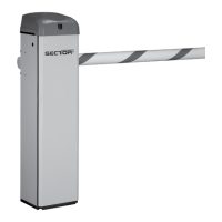
Identifies and labels the external parts of the SECTOR II barrier.
Details the components located within the electronics tray of the barrier.
Instructions and list of hardware provided for unpacking the barrier.
Explains how to determine and set the correct barrier orientation (left/right).
Details the steps and dimensions for preparing the concrete plinth for the barrier.
Instructions for physically mounting the barrier cabinet onto the prepared plinth.
Steps for attaching the boom pole to the barrier mechanism.
Procedures for ensuring the boom pole is perfectly horizontal after installation.
How to adjust the spring tension for proper barrier balance.
Steps to safely isolate power before performing wiring on the barrier.
Instructions for properly grounding the barrier unit for electrical safety.
Guides the connection of the 220V AC mains power supply to the barrier.
Procedures for installing various types of loop detectors for vehicle detection.
Initial steps to power on the barrier and its controller.
Guide to setting up and programming the barrier's control parameters.
How the controller assists in adjusting the spring tension for balance.
Configuring collision sensitivity settings for operational safety.
Configuration options for the automatic lowering function of the barrier.
Procedures for setting up and testing the installed loop detectors.
Key information to convey to the end-user regarding operation and safety.
An overview of the controller's menu structure and available features.
Detailed settings for loop detector functions, including alarms.
Configuration for controlling an external traffic light connected to the barrier.
Setup for indicating barrier operating states to external systems.
Settings for Ticket Vendor Interlock output functionality.
Configuration options for the barrier's courtesy lighting.
How the controller interacts with CLAWS spike modules for security.
Setting up time-based automatic activations and barring of operations.
Configuration of operating standards, controller type, and reset options.
Adding, deleting, and managing remote control transmitters for the barrier.
Schedule and steps for regular maintenance of the barrier system.
Inspection and tightening of mechanical components for proper function.
Procedure to check and adjust the spring tension for optimal balance.
Troubleshooting common installation and setup problems encountered on site.
Explains the meaning of diagnostic LEDs on the controller for fault finding.
Interpreting information shown on the controller's LCD display for system status.
Explains audible alerts from the buzzer and their corresponding meanings.
Technical specifications for different SECTOR II barrier models, including voltage and dimensions.
Details on the physical characteristics of the boom poles, such as material and weight.
Information on the fuse types and ratings used in various circuits of the barrier.
States that this page has been intentionally left blank.
Step-by-step guide to reconfigure the barrier for left-hand installation.
How to adjust the barrier's endstops for fail-safe or lock mode operation.
Instructions for installing FLUX 11-pin loop detectors into the barrier system.
Wiring diagrams for installing safety infrared beams to the barrier controller.
Various wiring configurations for different operational modes like Simplex and Complex.
Default parameter values for the South African (ZA) operating profile.
Explains the function of each terminal on the S-SERIES controller.
Describes optional additional devices that can be interfaced with the barrier for enhanced functionality.
| Brand | CENTURION SYSTEMS |
|---|---|
| Model | SECTOR II |
| Category | Other |
| Language | English |