TRG
COM
POWER SUPPLY
FOR DOOR STRIKE
EXTRA
HANDSETS
DOOR
STRIKE
HANDSETENTRY PANEL
See Note
Below
See Notes
See Note
Below
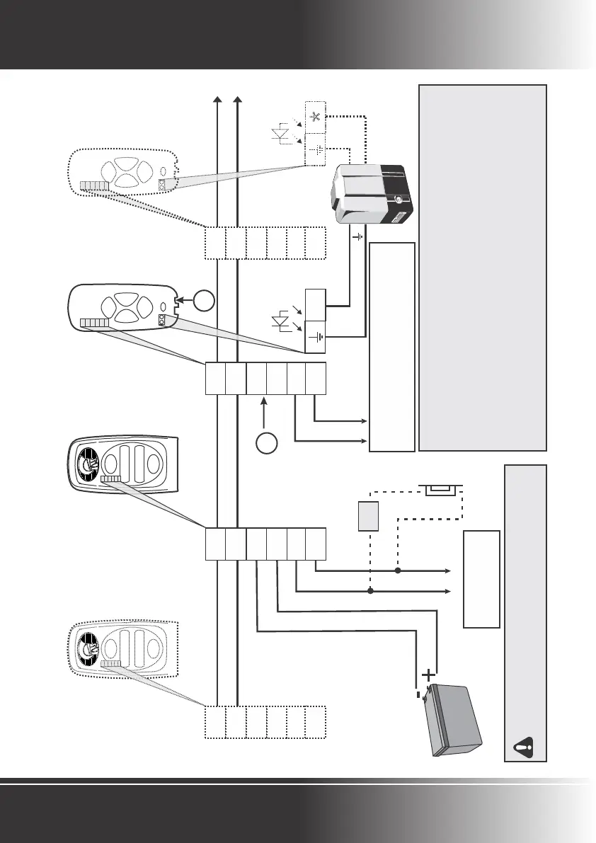
Potential-free normally-
open contact to
activate gate motor etc.
NO
2
1
+
-
COM
NO
2
1
+
-
COM
NO
2
1
+
-
COM
NO
2
1
+
-
COM
1
2
_
+
NO
COM
1
2
_
+
AUX
AUX
1
2
_
+
AUX
AUX
AUXILIARY OUTPUT/POTENTIAL-FREE NORMALLY-OPEN
- GATE PEDESTRIAN OPENING
- PILLAR LIGHT CONTROL
- ENTRANCE LIGHT CONTROL
NOTES:
Power Supply
1. Only one 12V DC Power Supply is typically needed to power the system.
2. Power can be connected to any component in the system.
3. The diagram shows the 12V Battery Supply of gate motor connected to the entry panel
to
power the system.
4. If power is being connected to the handset use either a mains adapter with a DC jack
compatible with the socket provided (A) or connect 12-14V DC to the terminals (B).
5. If the bus voltage (between terminals “1” and “2”) is lower than 8V DC, power needs
B
A
TO COMMON/NEGATIVE
TO STATUS
LED OUTPUT
*
*
NB: Have you considered using the POLOswitch
as a secure means of triggering the gate or door
1
2
_
+
NO
COM
BATTERY SUPPLY
GATE
MOTOR
Page 12 - POLOphone Intercom
WIRING DIAGRAM
 Loading...