f
NOTE
·
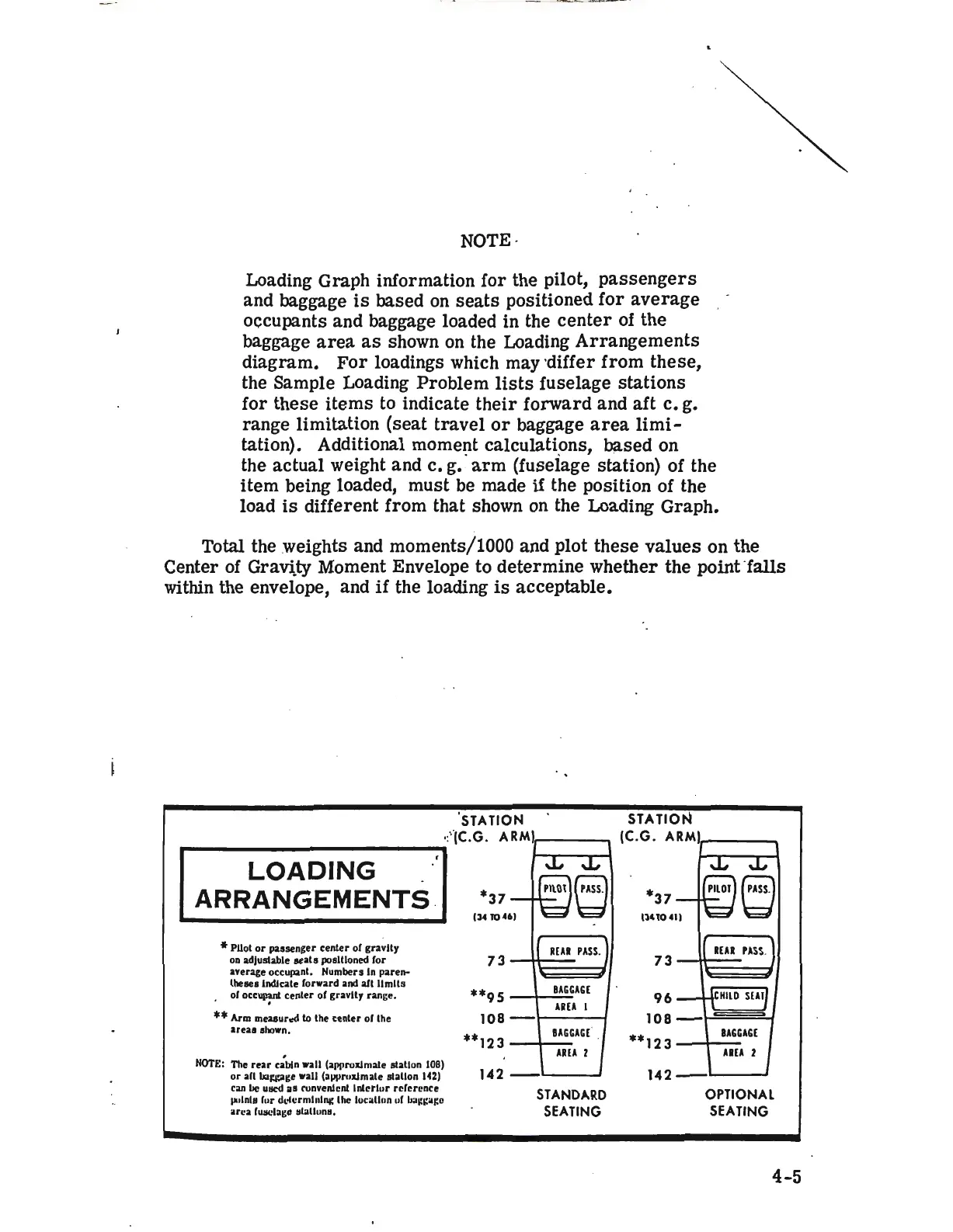
Loading Graph information for the pilot,
passengers
and baggage
is
based
on
seats
positioned
for
average
: -
occupants and baggage loaded in the
center
of the '
baggage
area
as
shown
on
the Loading
Arrangements
diagram.
For
loadings which may ·differ from these,
the Sample Loading Problem
lists
fuselage stations
for these
items
to
indicate their forward and aft c. g.
range limitation (seat travel
or
baggage
area
limi-
tation). Additional moment calculations, based on
the actual weight and c. g •. ·
arm
(fuselage station) of the
item
being loaded, must be made
if
the position of the
load
is
different from that shown
on
the Loading Graph.
Total the weights and moments/1000 and plot these values on the
Center
of
Gravlty Moment Envelope to determine
wh~ther
the point-
falls
within the envelope, and
if
the loading
is
acceptable.
0
STATION STATION
·:' (C.G. ARM)
1
____
(C.G.
ARMlr----.
..--------------------------.
LOADING
ARRANGEMENTS
.
* Pilot
or
passenger
center
of gravity
on
adjustable
seats
positioned for
average
occupant. Numbers In
paren-
theses lndJcate forward and aft
limits
. of
occuir;ant
center
or gravity range.
**Arm
meaaur..d
to
the
center
or the
areas
shown.
NOTE:
The
rear
c;btn
wall (a1Jt1roxlmate station
108)
or
aft
wwge
wall
(a1111ruxlmate
station
142)
can
lie
ulled u runvenlcnt
lnlctlur
reference
pulnla for
dLofcrmlnl111:
lhe loc;itlun ul ll:ii:i:;ii:e
uca
lllllClagc
11latlun11.
**95
BAGGAGE
AREA
I
108-
**123
BAGGAGE'
.
AREA
Z
142------
STANDARD
SEATING
**123
BAGGAGE
AREA
Z
142--'---~
OPTIONAL
SEATING
4-5