EasyManua.ls Logo

Cessna 402B 1973 - Fire Detection and Extinguishing System

Cessna 402B 1973
103 pages
Print Icon
To Next Page IconTo Next Page
To Previous Page IconTo Previous Page
Loading...
NOTE
The disengage
swi.tch removes
all
power
from
the
system and
places
motor and clutch
circuits
to
ground..,
Manual
Trim
- AS
REQUIRED.
FIRE
DETECTION
AND
EXTINGUISHING
SYSTEM
The
fire detection and
extinguishing system
consists of tJrree
major
components:
three heat sensitive
detectors located
in each
engine acces-
sory
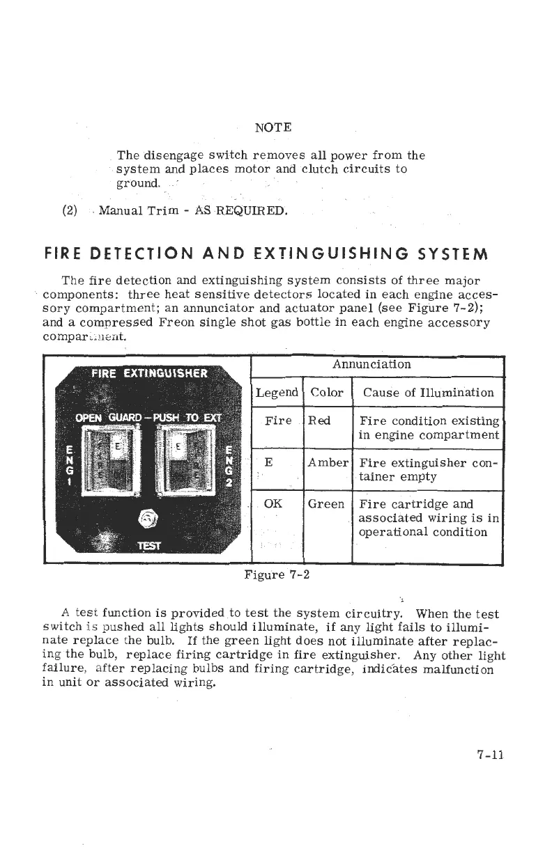
compartment; an annunciator
and actuator
panel
(see
Figure ?-2);
and
a
compressed Freon single shot
gas
bottle
in each engine
accessory
compartinent.
A test
function
is
provided
to
test the system
circuitry.
when the test
switch
is
pushed
all lights
should
illuminate,
if
any
light fails
to illumi-
nate
replace the
bulb.
rf the green
light does
not illuminate
after
replac-
ing
the
bulb,
repLace firing
cartridge
in
fire
extinguisher.
Any othei
tigtrt
failure,
after
replacing
bulbs
and firing
cartridge,
irdic-ates
malfunction
in
unit or associated
wiring.
(2)
Annunciation
Legend
Color
Cause of
Illumination
Fire Red
Fire
condition
existing
in
engine
compartment
E
Amber
Fire extinguisher
con-
tainer
e.mpty
OK Green Fire
cartridge and
assoclated
wiring
is in
operational
condition
Figure
7-2
7
-tl