Do you have a question about the Cessna 172 Skyhawk SERIES and is the answer not in the manual?
Provides a detailed description of the aircraft's construction and features.
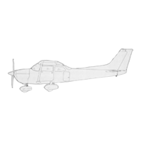
Specifies the model series covered by this manual.
Details the aircraft's high-wing, all-metal, semimonocoque construction and key features.
Lists leading particulars and dimensions based on gross weight for aircraft specifications.
Explains the use of station diagrams for locating equipment.
Presents a chart of recommended nut torque values for installation procedures.
Covers various aspects of ground handling, including towing, hoisting, and parking.
Outlines servicing procedures for fuel, engine oil, and other systems.
Details lubrication requirements for various aircraft components.
Specifies items to be inspected as part of routine maintenance.
Refers to figure 2-5 for lubrication requirements and supplements it with details.
Specifies cleaning and repacking intervals for wheel bearings.
Details lubrication requirements for nose gear torque links.
Outlines cleaning and lubrication procedures for the wing flap actuator jack screw.
Details inspection requirements for the fuel selector valve and drive shaft.
Overview of typical instrument installations and their respective operating systems.
Emphasis on troubleshooting and corrective measures for instrument systems.
Describes the instrument panel assembly, including stationary and shock-mounted panels.
Procedures for removing and installing the shock-mounted instrument panel.
Emphasizes the importance of shock-mounting for instrument service life.
Details the removal and installation of individual instruments.
Instructions for removing instruments from the panel.
General installation procedures, emphasizing proper tightening and connections.
Describes the pitot and static systems, including airspeed, vertical speed, and altimeter connections.
Emphasizes essential maintenance for pitot and static systems, focusing on cleanliness and security.
Outlines the procedure for inspecting and testing the static pressure system for leaks.
Describes the encoding altimeter and its connection to the static system.
Refers to Figure 15-2, Sheet 2 for encoding altimeter removal and installation.
Describes the true airspeed indicator and its operation with a conversion ring.
Instructions for installing and calibrating the true airspeed indicator.
Describes the mechanical tachometer and its drive shaft.
Describes the Bourdon tube-type oil pressure gage and its connection.
Details the Bourdon tube-type oil pressure gauge and its operation.
Troubleshooting chart for oil pressure gauge issues.
Describes the oil temperature gauge and its electrical connections.
Describes the oil temperature gauge's electrical operation.
Describes the carburetor air temperature gauge and its system.
Describes the resistance-bridge type carburetor air temperature gauge.
Troubleshooting chart for carburetor air temperature gauge issues.
Describes the magnetic type fuel quantity indicators and float-operated transmitters.
Procedures for removing and installing fuel quantity transmitters.
Troubleshooting chart for fuel quantity indicator issues.
Describes the electrically operated hourmeter and its actuation.
Describes the liquid-filled magnetic compass and its compensation.
Refers to Figure 15-5 for magnetic compass removal and installation.
Describes the stall warning system, including its adjustable plate and horn.
Refers to Figure 15-5 for stall warning system removal and installation.
Describes the turn coordinator as an electrically operated gyroscopic instrument.
Troubleshooting chart for turn coordinator issues.
Describes the turn-and-slip indicator as an electrically operated instrument.
Troubleshooting chart for turn-and-slip indicator issues.
Overview of the aircraft electrical systems.
Describes the 12-volt, single-wire, negative ground electrical system.
Describes the split bus bar that supplies power to equipment and electronic installations.
Describes the operation of the battery and alternator systems via the master switch.
Describes the ammeter's function in indicating current flow to or from the battery.
Details the battery's specifications and mounting.
Describes the 12-volt, 25 ampere-hour battery.
Describes the acid-proof battery box and its vent system.
Procedures for removing and installing the battery box.
Instructions for inspecting and cleaning the battery box.
Describes the battery contactor and its function.
Details the plunger-type contactor actuated by the master switch.
Procedures for removing and installing the battery contactor.
Describes the circuit used to close the contactor when the battery is weak.
Explains the components of the battery contactor closing circuit.
Describes the optional ground service receptacle for external power.
Details the ground service receptacle's polarity protection system.
Troubleshooting chart for starter engagement with ground power.
Troubleshooting chart for ground power failure to crank the engine.
Describes the alternator system, including the regulator and warning light.
Describes the 60-ampere alternator's specifications.
Details the alternator's construction and output rating.
Troubleshooting for heavy discharge indication or circuit breaker opening.
Troubleshooting for alternator system failure to charge the battery.
Troubleshooting for alternator overcharging the battery.
Describes the over-voltage system, including sensor switch and warning light.
Describes the voltage regulator's function and components.
Procedures for removing and installing the voltage regulator.
Lists the components of the aircraft lighting system.
Troubleshooting chart for various aircraft lighting issues.
Describes the landing and taxi light's location and control.
Procedures for removing and installing the landing and taxi light.
Instructions for adjusting the landing and taxi light.
Describes optional dual landing and taxi lights.
Details the optional dual landing and taxi lights and their controls.
Procedures for removing and installing dual landing and taxi lights.
Describes the navigation lights mounted on wing tips and vertical fin.
Refers to Figure 16-6 for navigation lights removal and installation.
Describes the strobe light's operation and power supply.
Refers to Figure 16-6 for strobe light and power supply removal and installation.
Describes the flashing beacon light's attachment, lamp, and resistor.
Refers to Figure 16-7 for flashing beacon removal and installation.
Describes the instrument flood light and dome light, including their controls.
Refers to Figure 16-8 for instrument and dome light removal and installation.
Describes the courtesy lights mounted on the underside of each wing.
Refers to Figure 16-8 for courtesy lights removal and installation.
Describes the compass and radio dial lights controlled by the instrument flood light switch.
Describes individual post lighting for instrument lighting.
Procedures for removing and installing post lamps.
Describes a remotely located, two-circuit transistorized dimming assembly.
Refers to Figure 16-9 for transistorized dimming assembly removal and installation.
Describes the adjustable map light and its controls.
Refers to Figure 16-10 for map light removal and installation.
Describes the control wheel map light mounted on the lower side of the control wheel.
Procedures for removing and installing the map light assembly.
Describes the pitot heater's function in preventing ice formations.
Describes the cigar lighter and its thermal-actuated circuit breaker.
Describes the ELT as a self-contained unit with dual emergency frequencies.
Explains the operation of the ELT's three-position switch.
Specifies the checkout interval for the ELT, including test procedures.
Procedures for removing and installing the ELT transmitter.
Transmitters with 4 cell battery packs can only be replaced with another 4 cell battery-pack.
Overview of structural repair criteria, equipment, and materials.
Details on materials used for structural repairs, including aluminum alloy types.
Covers wing structure, including skin, stringers, ribs, spars, and leading edge repairs.
Details on negligible, repairable, and replacement-requiring damage to ailerons.
Covers negligible, repairable, and replacement-requiring damage to wing flaps.
Details negligible, repairable, and replacement-requiring damage to elevators and rudder.
Covers fuselage structure and types of damage, including corrosion and wrinkles.
Describes repairable damage to bonded doors.
Outlines procedures for repairing firewall damage.
Covers engine mount description, general considerations, and repair of cradle damage.
Discusses replacement of damaged baffles.
Covers repair of cowling skins and reinforcement angles.
Refers to paragraph 18-13 for negligible damage criteria.
Outlines a typical wing stringer repair method.
Recommends replacement if a stringer requires more than one section splice.
Refers to paragraph 18-13 for negligible damage criteria.
Illustrates a typical auxiliary spar repair.
Recommends replacing auxiliary spars if damage requires repair between adjacent ribs.
Refers to paragraph 18-13 for negligible damage criteria.
Illustrates a typical wing rib repair.
Recommends replacing leading/trailing edge ribs or center ribs if damage is extensive.
Defines negligible damage for wing spars, excluding cracks and stress wrinkles.
Illustrates typical spar repairs and suggests using service parts or kits.
Recommends replacing complete wing spars if damage is not practicable to repair.
Refers to paragraph 18-13 for negligible damage criteria for elevators and rudder.
Outlines repairs for aileron leading edge skins and flat surfaces.
Recommends replacing complete skin panels if damage cannot be made between adjacent ribs.
Provides instructions for balancing ailerons after repair, replacement, or painting.
Refers to paragraph 18-13 for negligible damage criteria for elevators and rudder.
Describes flap repairs similar to aileron repairs and shows leading edge repair.
Recommends replacing flap parts if damage requires repair between adjacent ribs.
Refers to paragraph 18-13 for negligible damage criteria.
Shows a typical leading edge skin repair and suggests using epoxy filler.
Recommends replacing complete leading edge skin panels for extensive damage.
Defines negligible damage for elevator surfaces, excluding hinge fittings and structure.
Illustrates skin patches for elevator/rudder damage and mentions balancing.
Recommends replacing elevator/rudder assemblies for extensive damage.
Provides instructions for balancing elevators and rudders after repair or replacement.
Refers to paragraph 18-13 for negligible damage criteria.
Shows skin patches for fin damage and access methods.
Recommends replacing complete skin panels for extensive damage or compound curves.
Describes the fuselage construction, including bulkheads, stringers, and skin panels.
Refers to paragraph 18-13 for negligible damage criteria for fuselage.
Describes repairable damage to bonded doors using similar methods to riveted structure.
Discusses the impracticality of patch repairs for landing gear bulkheads due to stress and shape.
Describes evidence of damage after a hard landing and inspection procedures.
Describes the engine mount's construction and its attachment to the firewall.
Emphasizes the importance of high-quality welding for engine mounts due to vibration.
Outlines minor repair procedures for engine mount cradle damage.
States that engine mounting lugs and fittings must be replaced if damaged.
Discusses replacement of damaged baffles and the use of plate reinforcements.
Covers repair of cowling skins and reinforcement angles.
Outlines repair procedures for cowling skins, including stop-drilling cracks.
States that cowl reinforcement angles must be replaced if damaged.
Recommends using a specific repair kit for ABS components.
Contains standard factory materials listing and area of application for painting.
Basic steps for touch-up or painting of formed ABS plastic parts for interior.
Steps for touch-up or painting of exterior ABS plastic parts with acrylic topcoat.
Procedures for painting exterior parts with epoxy or polyurethane topcoat.
| Manufacturer | Cessna |
|---|---|
| Model | 172 Skyhawk |
| Engine | Lycoming IO-360-L2A |
| Horsepower | 180 hp |
| Wingspan | 36 ft 1 in (11.0 m) |
| Height | 8 ft 11 in (2.72 m) |
| Cruise Speed | 124 knots (143 mph, 230 km/h) |
| Range | 696 nmi (801 mi, 1, 289 km) |
| Seating Capacity | 4 |
| Length | 27 ft 2 in |
| Service Ceiling | 13, 500 ft (4, 100 m) |
| Maximum Takeoff Weight | 2, 550 lb (1, 157 kg) |
| Fuel Capacity | 56 US gal (212 L) |
| Rate of Climb | 720 ft/min (3.7 m/s) |