(~~~L402C
LANDING
GEAR
SYSTEM
SECTION
7
AIRPLANE
&
SYSTEMS
DESCRIPTIONS
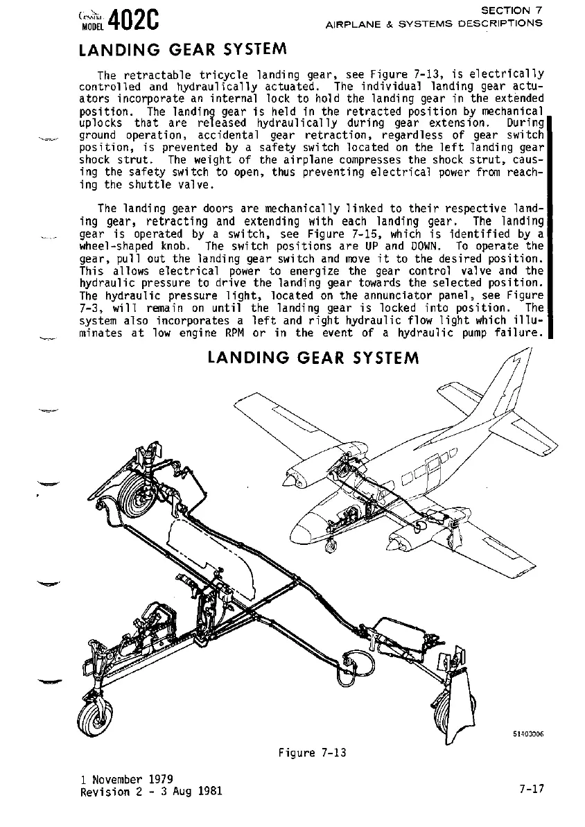
The
retractable
tricycle
landing
gear,
see
Figure
7-13,
is
electrically
controlled
and
hydraulically
actuated.
The
individual
landing
gear
actu-
ators incorporate
an
internal lock to
hold
the landing gear
in
the extended
position.
The
landing gear
is
held
in
the retracted position by mechanical
uplocks
that
are
released
hydraulically
during gear
extension.
During
ground opera
t;
on,
ace;
denta
1 gear
retract;
on. regard
less
of
gear switch
position,
;s
prevented by a
safety
switch
located
on
the
left
landing
gear
shock
strut.
The
weight of the airplane compresses the
shock
strut,
caus-
ing the safety switch to open, thus preventing
electrical
power
from
reach-
ing the
shuttle
valve.
The
landing gear doors are mechanically linked to
their
respective land-
ing
gear,
retracting
and
extending
with each
landing
gear.
The
landing
gear
is
operated
by
a switch, see Figure 7-15,
which
is
identified
by
a
wheel-shaped
knob.
The
switch positions
are
UP
and
DOWN.
To
operate the
gear,
pullout
the landing gear switch
and
move
it
to the desired position.
This allows
electrical
power
to energize the gear control valve
and
the
hydraulic pressure to drive the landing gear towards the selected position.
The
hydraulic pressure
light,
located
on
the annunciator panel, see Figure
7-3, will
remain
on
until the landing gear
is
locked into position.
The
system also incorporates a
left
and
right
hydraulic
flow
light
which
illu-
minates
at
low
engine
RPM
or
in the event of a hydraulic
pump
failure.
LANDING GEAR
SYSTEM
_.
-
Figure
7-13
1 November 1979
Revision
2 - 3
Aug
1981
51403006
7-17