'M~L402C
SECTION
7
AIRPLANE
&
SYSTEMS
DESCRIPTIONS
-
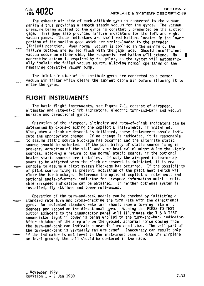
The
exhaust
air
side
of each
attitude
gyro
is
connected to the
vacuum
manifold thus providing a
smooth
steady
vacuum
for the gyros.
The
vacuum
pressu
re
be
i
n9
appl i ed
to
the
gyros
is
cons
tantl
y
presented
on
the
su
cti
on
gage. This
gage
also provides
failure
indicators for the
left
and
right
vacuum
pumps.
These
indicators
are
small red buttons located in the lower
portion of the suction
gage
Which
are spring-loaded to the extended
(failed)
position.
When
nonnal
vacuum
is
applied
in
the
manifold,
the
failure
oottons
are
pulled
flush
with
the
gage
face.
Should
insufficient
vacuum
occur
on
either
side,
the respective red button will extend.
No
I
corrective
action
is
required
by
the
pilot,
as
the system will automatic-
ally
isolate
the
failed
vacuum
source, allowing
normal
operation
on
the
remaining operative
vacuum
pump.
The
inlet
air
side of the
attitude
gyros are connected to a
common
vacuum
air
filter
which
cleans the ambient cabin
air
before allowing
it
to
enter
the gyros.
FLIGHT
INSTRUMENTS
The
basic
flight
instruments, see Figure 7-1,
consist
of airspeed,
altimeter
and
rate-of-climb
indicators,
electric
turn-and-bank
and
vacuum
horizon
and
directional
gyros.
Operation of the
airspeed,
altimeter
and
rate-of-climb
indicators
can
be
determined
by
cross-checking the
copilot's
instruments,
if
installed.
Also,
when
a climb
or
descent
is
initiated,
these instruments should
indi-
cate the appropriate change.
If
no
change
is
indicated,
it
is
reasonable
to
assume
static
source blockage
has
occurred
and
the
alternate
static
source should
be
selected.
If
the
possibility
of
static
source icing
is
present, actuation of the
stall
and
vent heat switch might deice the
static
sources, allowing a return to the
normal
static
source,
if
the optional
heated
static
sources are
installed.
If
only the airspeed
indicator
ap-
pears to
be
affected
when
the climb or descent
is
initiated,
it
is
rea-
sonable
to
assume
a
pitot
system blockage
has
occurred.
If
the
possibility
of
pitot
source icing
is
present, actuation of the
pitot
heat switch will
clear
the
ice
blockage. Reference the optional
copilot's
instruments
and
optional
angle-of-attack
indicator
for airspeed information
until
a
reli-
able airspeed indication
can
be
obtained.
If
neither
optional system
is
installed,
fly
attitude
and
power
references.
Operation of the turn-and-bank needle
can
be
checked
by
initiating
a
standard
rate
turn
and
cross-checking the turn
rate
with the
directional
gyro.
An
indicated standard
rate
turn should
show
a turning
rate
of 3
degrees per second
on
the
directional
gyro.
Pushing
the
PRESS-TO-TEST
button adjacent to the annunciator panel
will
illuminate the T &B
TEST
annunciator
light
if
power
is
being applied to the turn-and-bank
indicator.
After
shutdown
of the
airplane
on
the ground,
abnonnal
noise
cCflling
from
the turn-and-bank
can
indicate
a near
failure
condition.
The
ball
part
of
the turn-and-bank
is
virtually
failure
proof. Inaccuracy
can
result
only
if
the
indicator
is
not level in the instrument panel.
With
the
airplane
on
level ground, the ball should
be
centered in the race.
1
November
1979
Revision 1 - 2 Jan
1980
7-33
 Loading...