3
FR
INSTALLATION
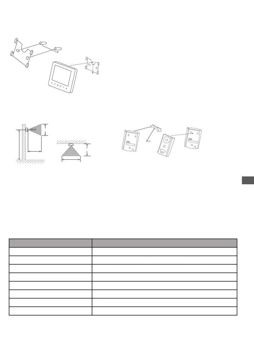
1. Indoor unit
1. Find a suitable location.
2. Install the installation plate for the monitor.
A: Drill a hole in the wall, insert the anchors.
B: Tighten the screws.
3. Connect the wiring.
4. Install the main unit on the back side of the installation plate.
2. Outdoor unit
1. Unscrew the lower screw, below the outdoor unit.
2. Install the protection plate of the outdoor unit.
A: Drill a hole in the wall, insert the anchors.
B: Tighten the screws. 3. Connect the wiring.
4. Install the main unit on the protection plate.
5. Screw the lower screw below the outdoor unit.
3. Wiring diagram
main monitor to
1 Outdoor unit / connector 1
2 Outdoor unit / connector 2
A Secondary monitor / connector A
B Secondary monitor / connector B
R Additional camera / red wire
B Additional camera / black wire
W Additional camera / white wire
Y Additional camera / yellow wire
+/-
150 cm
+/- 180 cm
+/- 180 cm
+/- 65 cm
+/- 110 cm
+/- 50 cm
+/- 50 cm
Connecting wire instruction
option
Y
OUTDOOR CAMERA
1R
1W
1B
1Y
R
W
B
POWER
MONITOR
SW1
LK-
SW2
LK+
1R
1Y
1W
1B
Doorlock
Outside Gate
OUT
IN
Y = Jaune, Geel, Amarillo, Amarelo
B = Brun, Bruin, Marrón, Castanho
W = Blanc,Wit, Blanco, Branco
R = Rouge, Rood, Rojo, Vermelho
85,8mm
50 mm
 Loading...