EasyManua.ls Logo

Chad Valley Straight Slide User Manual

Chad Valley Straight Slide
12 pages
To Next Page IconTo Next Page
Page #1 background imageLoading...
Page #1 background image
Straight Slide
Assembly & User Instructions - Please keep for future reference
Important - Please read these instructions fully before assembly or use
These instructions contain important information which will help you get the best from your
product and ensure safe and correct assembly, use and maintenance.
If you need help or have damaged or missing parts, call the Customer Helpline: 01291 650581
Warning
Age: 3+ years
910/8453,910/8446
Question and Answer IconNeed help?

Do you have a question about the Chad Valley Straight Slide and is the answer not in the manual?

Chad Valley Straight Slide Specifications

General IconGeneral
BrandChad Valley
ModelStraight Slide
CategoryPlay Sets & Playground Equipment
LanguageEnglish

Summary

Product Parts Identification

Straight Slide Assembly Instructions

Step 1: Insert Handle Bars

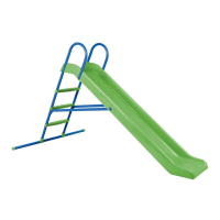
Insert handle bar (B) into the grooves on slide (A).

Step 2: Assemble Handle Bar (Rear)

Fix rear hole with 40mm screw (N) and nut (H).

Step 3: Assemble Handle Bar (Front)

Fix front hole with 40mm screw (N) and nut (H).

Step 4: Assemble Plug

Insert plug (L) and repeat on the other side.

Step 5: Assemble Stiles

Insert stiles (C) into the main body.

Step 6: Assemble First Step

Insert upper step (F) onto the stiles.

Step 7: Fix Upper Step

Fix upper step (F) with 45mm screw (M) and nut (H).

Step 8: Assemble Remaining Steps

Insert middle and lower steps (F).

Step 9: Connect Steps to Handle Bars

Fix steps (F) to handle bars with 45mm screw (M) and nuts (H).

Step 10: Position Connector Tube

Place connector tube (D) in position.

Step 11: Fix Connector Tube to Stile

Fix connector tube (D) on stile (C) with screw (N) and cap nut (J).

Step 12: Fix Connector Tube to Slide

Attach connector tube (D) to slide (C) with washer (I) and screw (N).

Step 13: Assemble Base Connectors

Fit base connectors (G) onto base tube (E) and attach to stiles (C).

Step 14: Secure Base Assembly

Fix base assembly with 45mm screws (M) and nuts (H).

Step 15: Assemble Base End Caps

Assemble end caps (K) in both sides of base tube (E).

Product Safety and Usage Guidelines

General Warnings and Precautions

Warnings on packaging materials, side bar use, and environment.

Load and Age Restrictions

Maximum load capacity (50 kg) and recommended age (3+ years).

Installation and Placement Guidelines

Advice on level surface placement and avoiding obstructions.

Usage and Maintenance Checks

Instructions for safe use, regular checks, and part replacement.

Supervision and Instruction Retention

Requirements for adult supervision and keeping instructions for future reference.