2
ALIGNING THE SAFETY SENSORS
1. Plug in the opener. The indicator lights in both the sending and receiving
eyes will glow steadily if wiring connections and alignment are correct.
NOTE: The sending eye amber indicator light will glow regardless of
alignment or obstruction. If the green indicator light in the receiving
eye is off, dim, or flickering (and the invisible light beam path is not
obstructed), alignment is required.
2. Loosen the sending eye wing nut and readjust, aiming directly at the
receiving eye. Lock in place.
3. Loosen the receiving eye wing nut and adjust sensor vertically and/or
horizontally until it receives the sender’s beam. When the green indicator
light glows steadily, tighten the wing nut.
TROUBLESHOOTING THE SAFETY SENSORS
1. If the sending eye indicator light does not glow steadily after installation,
check for:
• Electric power to the opener.
• A short in the white or white/black wires. These can occur at staples,
or at screw terminal connections.
• Incorrect wiring between sensors and opener.
• A broken wire.
2. If the sending eye indicator light glows steadily but the receiving eye
indicator light doesn't:
• Check alignment.
• Check for an open wire to the receiving eye.
3. If the receiving eye indicator light is dim, realign either sensor.
NOTE: When the invisible beam path is obstructed or misaligned while the
door is closing, the door will reverse. If the door is already open, it will not
close. The opener lights will flash 10 times. (If bulbs are not installed, 10
clicks can be heard.) See page 1.
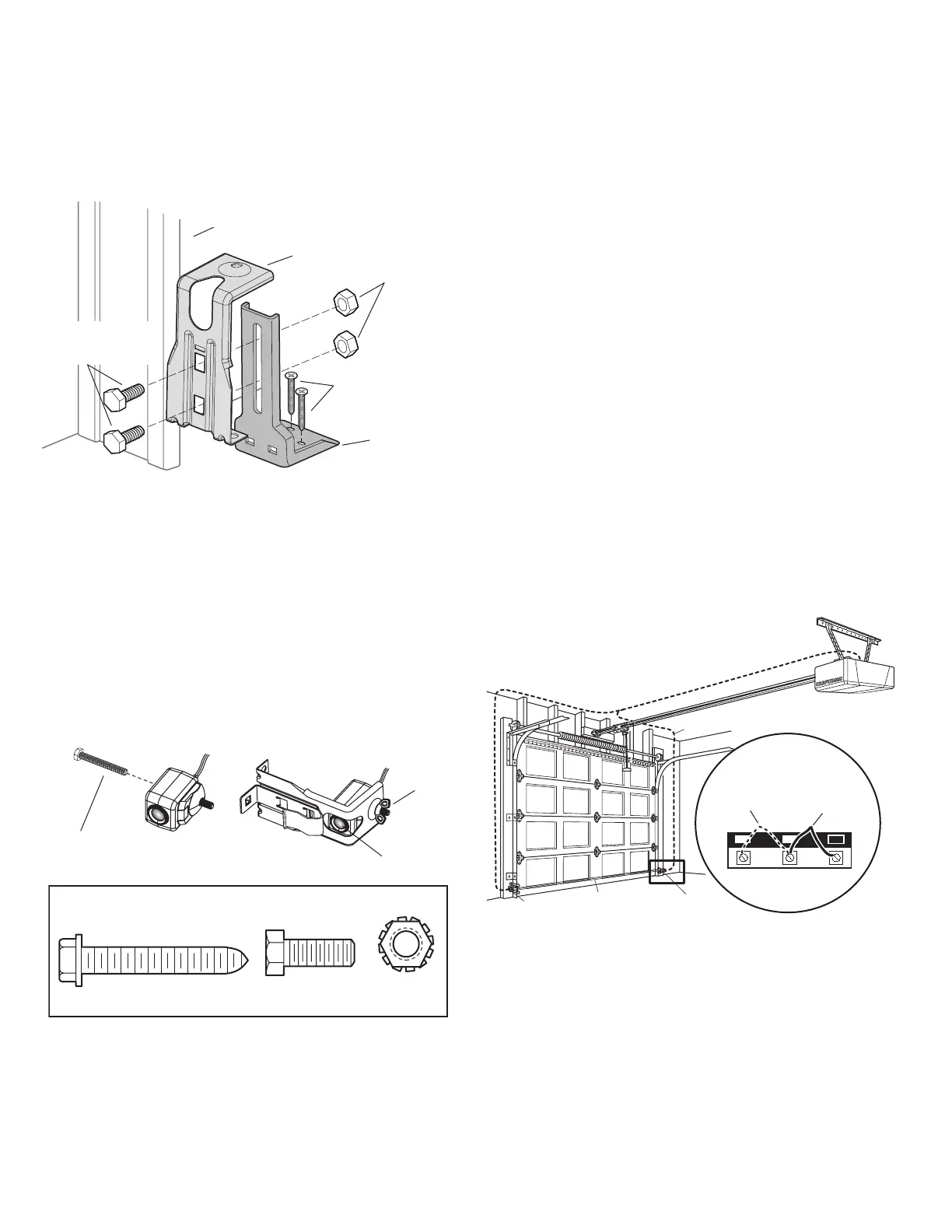
Figure 6: Connect Wire to Opener Terminal Screws
1 2
3
Bell Wire
Connect Wire to Opener
Terminal Screws
Door Control
Connections
(dotted line)
Sensor
Connections
Opener Terminal Screws
Sensor
Sensor
Invisible Light Beam
Protection Area
FLOOR INSTALLATION WITH EXTENSION BRACKET
1. Use wood blocks or extension brackets to elevate sensor brackets so the
lenses will be 4-6" above the floor.
2. Carefully measure and place right and left assemblies at the same
distance out from the wall. Be sure all door hardware obstructions are
cleared.
3. Fasten to the floor with concrete anchors (Figure 4).
Figure 4: Floor Mount (Right Side)
Extension
Bracket
Sensor
Bracket
Inside Garage Wall
(Provided with
Attach with concrete
anchors (not provided)
(Provided with
extension bracket)
MOUNTING AND WIRING THE SAFETY
SENSORS
1. Slide a 1/4"-20x1/2" carriage bolt head into the slot on both sensors.Use
wing nuts to fasten sensors to brackets, with lenses pointing toward each
other across the door. Be sure the lens is not obstructed by a bracket
extension (Figure 5).
2. Finger tighten the sensor wing nuts.
3. Run the wires from both sensors to the opener. Use insulated staples to
secure wire to wall and ceiling.
4. Strip 1/4" of insulation from each set of wires. Separate white and
white/black wires sufficiently to connect to the opener terminal screws:
white to 2 and white/black to 3 (Figure 6).
Figure 5: Safety Sensor Hardware
Hardware Shown Actual Size
1/4" x 1-1/2"
Lag Screw (4)
1/4" - 20 x 5/8"
Hex Bolt (2)
1/4" - 20
Lock Nut (2)
1/4" - 20 x 1/2"
Carriage Bolt
Lens