THIS RADIO CONTROL WILL NOT WORK WITH ‘PUSH TWICE TO CLOSE' DOOR OPENERS.
The Model 85 Transformer may be required if if you your garage door opener Is a brand OTHER THAN THAN Lift-
Master, Chamberlain or Sears.
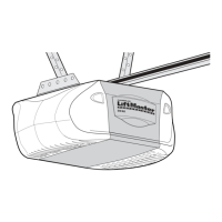
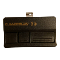
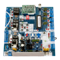
RADIO CONTROLS consist of a transmitter and a receiver. The transmitter sends a coded signal from outside the garage.
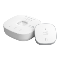
The receiver, installed inside the garage, accepts the transmitted signal and starts the door opener.
When installing two or more receivers in a garage, position them at least 10 feet apart to prevent electronic interference.
Self service of radio controls is not recommended. If service is needed, follow instructions on Page 2.
INSTALL THE RECEIVER OUT OF THE REACH OF CHILDREN. DO NOT ALLOW CHILDREN TO OPERATE
RECEIVER OR TRANSMITTER. SERIOUS PERSONAL INJURY FROM A CLOSING GARAGE DOOR MAY
RESULT FROM MISUSE OF THE OPENER.
DISCONNECT POWER TO OPENER BEFORE INSTALLING RECEIVER OR SETTING/CHANGING
CODE.
The receiver may be installed in one of two ways: 1. attached to an inside wall of the garage with connecting bell
wire (not supplied) 2. mounted directly on the door opener with clips provided. NOTE: Receiver and transmitter
are factory preset with matching codes.
CAUTION: Do not attempt to open receiver back panel. NO USER SERVICEABLE
PARTS
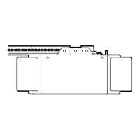
MOUNTING RECEIVER ON OPENER
Make sure antenna wire is fully extended downward below bottom
of case.
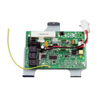
Loosen the three receiver terminal screws labeled 1, 2 and 3.
Insert one end of each mounting clip under a terminaL Make sure
the clip is positioned to clear receiver flange as shown. Do not
retighten at this time.
Loosen the (2) push button terminal screws on the opener as well
as the adjacent terminal screw which supplies the power. (These
terminals should also be marked 1, 2 and 3).
NOTE: Terminals 1, 2 and 3 on the receiver MUST be
connected to terminals 1, 2 and 3 on opener.
Leaving push button wiring in place, insert other ends of
mounting clips under opener screws.
If the terminal sequence on your opener does not match,
turn the receiver around (so back is facing out) and
complete connection.
Retighten terminal screws on opener and receiver.
Reconnect power to the opener. The receiver push button should
light. If it does not use Transformer Model 85.
NOTE: With Transformer Model 85, use a 2-terminal
connection ONLY. Attach clips to receiver terminals 1
and 2 and to opener terminals used for push button
controls.
It using Transformer Model 85, plug the transformer into
120 Volt outlet
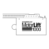
MOUNTING RECEIVER ON GARAGE WALL
The receiver has top and bottom installation flanges. Make sure
antenna wire is fully extended downward below the bottom of
case.
Fasten receiver to an inside garage wall with wood screws
provided. A convenient place is alongside service door and OUT
OF THE REACH OF CHILDREN.
Connect one end of 3-strand bell wire to receiver terminals 1, 2
and 3. The other end must be connected to the two opener
terminals used for push button controls and the adjacent terminal
which supplies the power. Use insulated staples to secure bell
wire between receiver and opener.
Reconnect power to the opener. The receiver push button should
light. If it does not use Transformer Model 85.
NOTE: With Transformer Model 85 use a 2-wire connection
ONLY. Attach bell wire to receiver terminals 1 and 2 and to
opener terminals used for push button controls.
If using Transformer Model 85, plug the transformer into a
120 Volt outlet.
OWNERS MANUAL
Model 100 (with 1 transmitter) and Model 100-2 (with 2 transmitters)
Lift-Master Universal Radio Control
Manufactured under 1 or more of the following US patents
3,445,848; 3,906,348; and 4,037,201