EasyManua.ls Logo

Chamberlain LiftMaster K001A6039 User Manual

Chamberlain LiftMaster K001A6039
6 pages
To Next Page IconTo Next Page
Page #1 background imageLoading...
Page #1 background image
APPLICATION REQUIREMENTS:
This modification is available to all LA400 North American gate
operators.
FUNCTION:
Allows existing LA400 control board in the field to be replaced or
upgraded with a new LA400 control board.
INSTALLATION INSTRUCTIONS
REMOVE EXISTING BOARD
1. Remove screws in each corner and open control box cover
(Figure 1).
2. Disconnect terminals leads to both batteries and the 24VAC or
solar input at the board.
3. Remove the coaxial cable going to the antenna at the board F
connector (Figure 2).
4. Remove all quick connect terminals in use to the logic board
(Figure 2).
• Wiring terminals
• Motor connectors
• Alarms
• Reset terminals
NOTE: Remember location of all wire connections for
reinstallation.
5. Disconnect the earth ground wire from the board
connector (J4).
6. Remove the screws (4) that fasten the control board to the
mounting bracket and remove the existing control board.
To prevent possible SERIOUS INJURY or DEATH from
electrocution or fire, disconnect power at the fuse box BEFORE
proceeding.
WARNING
CAUTION
WARNING
WARNING
Control Board
Replacement Kit
Screws
Batteries
Mounting
Bracket
Cover
Logic Board
Figure 1
1
K001A6039
Question and Answer IconNeed help?

Do you have a question about the Chamberlain LiftMaster K001A6039 and is the answer not in the manual?

Chamberlain LiftMaster K001A6039 Specifications

General IconGeneral
Model NumberK001A6039
BrandChamberlain LiftMaster
Battery TypeCR2032
CompatibilityLiftMaster garage door openers
Frequency315 MHz

Summary

INSTALLATION INSTRUCTIONS

REMOVE EXISTING BOARD

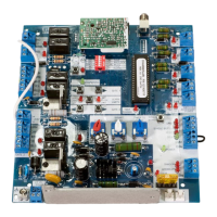
Steps to safely remove the existing control board from the enclosure.

INSTALL NEW BOARD

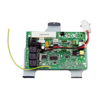
Instructions for installing the new control board and reconnecting wires.

COMPLETE THE INSTALLATION

Final steps for powering up, setting DIP switches, and testing the operator.

PROGRAM LIMITS

PROGRAMMING REMOTE

COMPATIBLE REMOTES

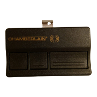
List of compatible remote control models for the 315MHz system.

TROUBLESHOOTING

OPERATOR IS DEAD

Diagnosing issues when the operator shows no signs of power.

OPERATOR DOES NOT RUN (Radio command)

Troubleshooting why the unit does not respond to radio commands.

OPERATOR DOES NOT RUN (SBC command)

Troubleshooting why the unit does not respond to single button control.

MOTOR DOES NOT RUN

Diagnosing motor issues when relays click but the operator does not move.

GATE STOPS AND REVERSES RIGHT AFTER IT STARTS MOVING

Identifying causes for sudden gate reversal.

GATE STOPS RUNNING RIGHT AFTER IT STARTS MOVING (BATTERY RUN)

Troubleshooting gate operation issues during battery backup.

GATE OPENS BUT DOES NOT CLOSE

Diagnosing why the gate fails to close.

GATE RUNS TOO SLOW

Addressing issues where the gate operates at reduced speed.

GATE DOES NOT CLOSE AUTOMATICALLY

Resolving problems with automatic gate closing.

GATE WON'T STAY OPEN WHEN USING FIRE INPUT

Fixing issues related to the fire input function.

INTERRUPT LOOP DOES NOT ACT PROPERLY

Troubleshooting problems with the interrupt loop sensor.

EXIT LOOP (FREE EXIT) DOES NOT OPEN GATE

Resolving issues where the free exit loop fails to open the gate.

MAGLOCK DOES NOT WORK

Diagnosing why the maglock is not holding gates securely.

DIAGNOSTIC CODES

Interpreting system diagnostic codes indicated by LED blink patterns.

Related product manuals