EasyManua.ls Logo

Channel Vision DSK-XXXXC - User Manual

Channel Vision DSK-XXXXC
19 pages
Print Icon
To Next Page IconTo Next Page
Loading...
DSK
DSK-XXXXC
DSK-XXXXP
-XXXXA
Telephone Entry Door Intercom
5
1
1
2
3
4
5
6
7
8
9
*
0
#
(T
Operating Voltage - Keypad: 12vDC 100mA
Operating Voltage - Communication: 12vDC 60mA
Operating Voltage - IP Camera: POE 802.3af or 12vDC 500mA
Cable Requirements - IP Camera: 1 CAT5/6 with POE for camera
Cable Requirements- Communication: 1 18/2 power wire for amplified companion
board, button & keypad
2 Conductor CAT5/6 for companion board
(communication)
ypical at 77º)
Question and Answer IconNeed help?

Do you have a question about the Channel Vision DSK-XXXXC and is the answer not in the manual?

Summary

DSK Series Keypad Programming

Keypad Configuration

Configuration Overview

Programming System Setup

Configuring Output A

Steps to configure Output A for CCTV/External Light or Auxiliary Device.

Programming System Setup (Continued)

Configuring Output B

Steps to configure Output B for CCTV/External Light or Auxiliary Device 2.

Normal System Operation

Keypad LED Status Indicators

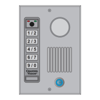
Explains keypad LED indicators, user commands, and tamper alarm.

Programming Individual Users

Adding a New User

Step-by-step guide to add new users with specific authorizations.

Programming Individual Users (Continued)

Integrating the ST-C5 IDS

Integrating the TE110 DS

Typical Hook-Ups

Troubleshooting

Channel Vision DSK-XXXXC Specifications

General IconGeneral
CategoryIntercom System
ModelDSK-XXXXC
ManufacturerChannel Vision
Voltage12-24V AC/DC
Operating Temperature-10° to 50° C (14° to 122° F)
MountingWall mount
CompatibilityChannel Vision Intercom System
Power12-24V AC/DC

Related product manuals