8E
Boot
Retainer
Nut
Ball
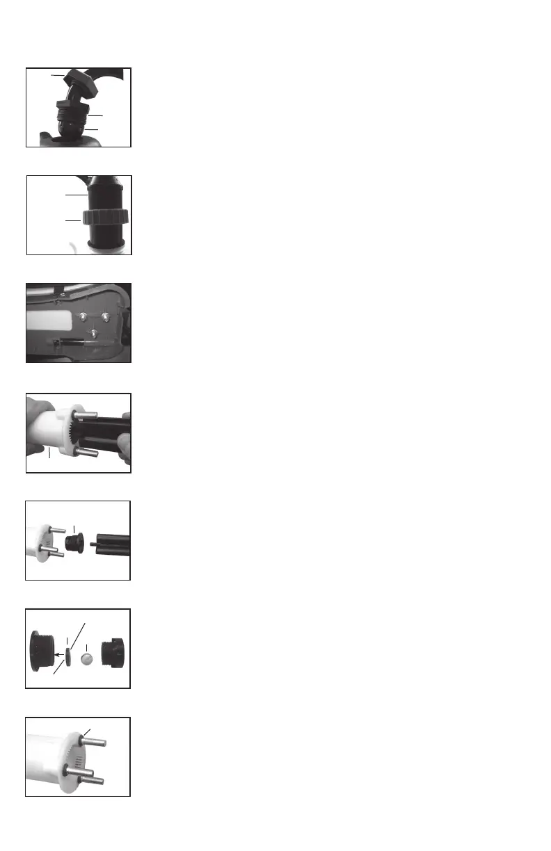
Figure 1
1) Insure the tank and pressure chamber contents are emptied and pressure
has been released in the pressure chamber. To release pressure in the
pressure chamber activate shut-off valve and release all pressure.
2) Disconnect linkage arm from the top of the pump assembly (see section
covering Installing The Pump Handle). (Figure 1).
Figure 2
3) Loosen pump locking ring and remove entire pump assembly from tank
(Figure 2).
PISTON CYLINDER DISASSEMBLY AND REBUILD
4) Remove the three bolts/washers attaching the piston cylinder to the bottom
of the tank (Figure 3).
5) Reach in through the tank ll opening and remove the piston cylinder.
6) Remove check valve cartridge assembly from bottom of piston cylinder
utilizing pump handle clip (clip has flat blade incorporated into end). Place flat
blade into slot in bottom of cartridge and unscrew (Figure 4 and 5).
7) Once cartridge has been removed it can either be replaced as an assembly or
rebuilt.
8) To rebuild disassemble two halves of cartridge and replace seal and/or
ball. Replace cartridge (Figure 6). The seal mounts inside the larger of the two
halves of the cartridge. The seal counterbore side mounts into the grooves in
the cartridge halve. Pump performance my be affected if this is not assembled
correctly.
9) At this point the piston cylinder itself and/or piston cylinder stud gaskets
can be replaced. The piston cylinder stud gaskets must be oriented correctly or
leakage may result (Figure 7).
10) Reassemble piston cylinder using washers and bolts on the underside of
the base.
11) Replace pump assembly into tank and into the piston cylinder which is
mounted on the bottom of the tank (see important notes regarding gasket and
felt washer in Pump and Disassembly and Rebuild section). Be careful not to
damage the plunger seal as it seats into the piston cylinder. It is recommended
that you look through the tank ll opening while performing this to achieve better
alignment. If necessary you can also reach in and use your hand to guide the
plunger seal into the piston cylinder.
12) Position the pump outlet (hose connection) in the desired position. Tighten
the pump retaining ring onto the tank.
13) Connect linkage arm to the top of the pump assembly (see section covering
Installing the Pump Handle)
Figure 5
Piston Cylinder
Check Valve
Flat side
Seal
Ball
Counterbore Side
Figure 6
Figure 7
Stud Gaskets
Figure 3
Figure 4
Pressure
Chamber
Pump
Locking
Ring