EasyManua.ls Logo

Char-Broil PATIO BISTRO 180 User Manual

Char-Broil PATIO BISTRO 180
20 pages
To Next Page IconTo Next Page
Page #1 background imageLoading...
Page #1 background image
42805104 ENG_FRE_SPA REV.10 • 08.05.13
CHARBROIL, LLC. COLUMBUS, GA
®
PATIO BISTRO 180 (LP GAS)
ELECTRONIC IGNITION MODULE REPLACEMENT PROCEDURE
MARCHE À SUIVRE POUR REMPLACER LE MODULE D'ALLUMAGE ÉLECTRONIQUE
PROCEDIMIENTO DE REEMPLAZO DEL MÓDULO DE ENCENDIDO ELECTRÓNICO
For Model Numbers: / Pour les numéros de modèle : / Para los números de modelo:
12601713
13601833
Have Questions? Need Assistance?
Call us at 1-866-671-7988
An instructional video demonstrating this procedure is available at www.charbroil.com/gas-
patio-bistro-recall.html
Des questions? Avez-vous besoin d'aide?
Appelez-nous au 1-866-671-7988
Une vidéo expliquant cette marche à suivre est mise à votre disposition au
www.charbroil.com/gas-patio-bistro-recall.html
¿Tiene preguntas? ¿Necesita asistencia?
Llámenos al 1-866-671-7988
Puede ver el video instructivo que describe este procedimiento en: www.charbroil.com/gas-
patio-bistro-recall.html
English: Pages 2-7 and 20
Français: Pages 8-13 et 20
Español: Páginas 14 a 19 y 20

Other manuals for Char-Broil PATIO BISTRO 180

Question and Answer IconNeed help?

Do you have a question about the Char-Broil PATIO BISTRO 180 and is the answer not in the manual?

Char-Broil PATIO BISTRO 180 Specifications

General IconGeneral
TypeElectric Grill
Cooking Area180 sq. in.
Heat ControlAdjustable Temperature Control
Fuel TypeElectric
ColorBlack
MaterialSteel
Ignition TypePush-button

Summary

Electronic Ignition Module Replacement Parts and Tools

Parts List

Lists all components included in the electronic ignition module replacement kit.

Tools Required

Specifies tools needed but not supplied with the replacement kit.

Electronic Ignition Module Replacement Procedure

Step 1 - Remove LP Cylinder and Grease Tray

Detach the LP gas cylinder and remove the grease collection tray.

Step 2 - Remove Battery Cap and Battery

Unscrew and remove the battery cap and the battery.

Step 3 - Remove Electronic Ignition Module Wiring

Disconnect the three wires from the old electronic ignition module.

Step 4 - Remove Electronic Ignition Module

Detach the old ignition module by removing its securing nut.

Step 5 - Install Electronic Ignition Module Bracket

Assemble and attach the new ignition module bracket to the grill leg.

Step 6 - Install New Electronic Ignition Module

Mount the new ignition module onto the bracket and secure it.

Step 7 - Install Electrode Wire to Electronic Ignition Module

Connect the electrode wire to the new electronic ignition module.

Step 8 - Install Ground Wire to Electronic Ignition Module

Attach the ground wire connector to the new ignition module.

Step 9 - Install Ground Wire to Rear Right Leg Screw

Secure the ground wire's ring connector to the right rear leg bracket screw.

Step 10 - Reinstall Battery and Battery Cap

Reinsert the battery and screw back on the battery cap.

Step 11 - Verify Proper Operation

Test the ignition by pressing the button to check for a spark.

Step 12 - Apply New Lighting Instruction Labels

Affix the new lighting instruction labels to the regulator.

Step 13 - Cut Old Ignition Wires at the Switch

Cut the old red and black ignition wires near the switch.

Step 14 - Reinstall LP Cylinder and Grease tray

Reattach the LP cylinder and the grease collection tray.

New Lighting Instruction Supplement

Ignitor lighting Instructions

Detailed steps for lighting the grill using the electronic ignition.
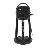
Related product manuals