Do you have a question about the CHCNAV CHC CTS-112R4 and is the answer not in the manual?
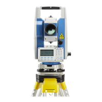
Identifies and labels all physical parts of the total station instrument.
Explains the function of each key on the instrument's keypad.
Defines the meaning of various symbols shown on the instrument's display.
Details the operations and functions of soft keys in different modes.
Explains functional keys for the Distance measurement interface.
Explains functional keys for the Coordinates measurement interface.
Accesses special settings like contrast, illumination, and tilt compensation.
Instructions for turning the instrument on and off.
Enables and configures tilt correction for accurate angle measurements.
Selecting different modes for distance measurement and reflector types.
Setting the prism constant for accurate distance measurements.
Importance and setup of atmospheric correction for measurement accuracy.
Setting minimum angle and distance units for measurements.
Setting and checking the instrument constant (K) for accuracy.
Instructions for safely unpacking and storing the instrument.
General procedure for mounting and leveling the instrument on a tripod.
Detailed steps for leveling and centering using a plumb bob.
Detailed steps for leveling and centering using the laser plummet.
Loading, unloading, charging, and checking battery status.
Steps for attaching and removing the instrument from the tribrach.
Guide to inputting numbers and text via the instrument's keypad.
Step-by-step process for measuring horizontal and vertical angles.
How to switch between right and left horizontal angle displays.
Methods to set a reference horizontal angle.
Holding the current horizontal angle reading as a reference.
Inputting a specific horizontal angle value using the keypad.
Switching between vertical angle and slope percentage displays.
Performing repeated angle measurements for improved accuracy.
Switching between azimuth and vertical angle display formats.
Initiating distance measurements and understanding EDM status indicators.
Selecting different distance measurement modes like Fine.S, F.3, etc.
Using the stakeout function to lay out points based on measured distances.
Overview of the four offset measurement modes.
Measuring coordinates of inaccessible points using angle offsets.
Measuring distances to points offset from a reference target.
Measuring coordinates of points on a plane or plane edges.
Measuring coordinates of a column's center using offset points.
Steps for measuring unknown coordinates after setting up the instrument.
Defining the instrument's position (occupied point) in the coordinate system.
Inputting and saving the instrument's height for accurate measurements.
Inputting and saving the target's height for Z coordinate acquisition.
Steps for selecting files, setting points, and starting data collection.
How to select or call up files for data collection.
Methods for setting occupied and backsight points in data collection.
Example of setting the occupied point from stored coordinate data.
Overview of offset measurement modes within data collection.
Measuring coordinates of inaccessible points via angle offsets.
Measuring distances to points offset from a reference target.
Measuring coordinates of points on a plane or plane edges.
Measuring coordinates of a column's center using offset points.
Settings for automatic coordinate calculation and data collection sequence.
Steps for performing stakeout operations using coordinate data.
Essential setup steps before commencing stakeout procedures.
Setting the grid factor for accurate stakeout calculations.
Methods for setting the instrument's occupied point for stakeout.
Methods for setting the backsight point for stakeout operations.
Using the side shot method to measure new points' coordinates.
Determining the instrument's position using known points and measurements.
Measuring target height without direct prism placement.
Steps for REM measurement when the prism height is known.
Steps for REM measurement when the prism height is unknown.
Measuring distances and differences between two prisms.
Procedure for MLM-1 measurement to find distances between points.
Using coordinate files for Tie distance measurements.
Setting the vertical (Z) coordinate for the occupied point.
Setting occupied point Z coordinate using an existing coordinate file.
Setting occupied point Z coordinate manually without a file.
Calculating the area of a closed figure.
Calculating area using data from a coordinate file.
Obtaining coordinate data relative to an origin and a defined line.
Configuring measurement units for feet, angle, distance, and temperature.
Setting power-on mode, distance mode, and coordinate display order.
Configuring minimum readings, auto power off, and buzzers.
Checking memory, formatting, and managing files.
Steps to create a new project file for data storage.
How to rename existing project files.
Procedures for deleting selected project files.
Exporting project files in TXT, DAT, and CSV formats.
Transferring data to a computer using a USB cable.
Loading coordinate and code data from a computer to the instrument.
Inspecting and adjusting plate and circular bubble levels for accuracy.
Adjusting the reticle for precise sighting and alignment.
Checking and adjusting the perpendicularity of the line of sight to the horizontal axis.
Checking and compensating for vertical index difference errors.
Adjusting vertical angle zero datum and index difference.
Adjusting for transverse axis error affecting the sight angle.
Inspecting and adjusting the optical plummet for centering.
Inspecting and adjusting the instrument constant (K) for accuracy.
Checking and adjusting the alignment of line of sight and photoelectric axis.
Instructions and safety warnings for reflectorless EDM measurements.
Adjusting the tribrach leveling screw for stability.
Checking tribrach adapter and prism pole for proper function.
| Type | Total Station |
|---|---|
| GPS | Yes |
| GLONASS | Yes |
| Galileo | Yes |
| BeiDou | Yes |
| QZSS | Yes |
| SBAS | Yes |
| Battery Life | Up to 8 hours |
| Angle measurement accuracy | 2" |
| Laser Plummet | Yes |
| Communication Interfaces | USB |
| Humidity | 95% non-condensing |