Do you have a question about the Chicago Pneumatic CP9361 and is the answer not in the manual?
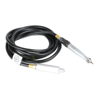
Provides basic details and context about the engraving pen and its features.
Information on accessing the company website for additional product details and resources.
Summary of maintenance, lubrication, and disposal guidelines for the engraving pen.
Instructions on how to switch between the stylus and chisel attachments.
Guidance on the correct method for sharpening the engraving pen's stylus.
Details on the process of hardening chisel blanks for durability.
Instructions and tips for operating the engraving pen effectively during use.
Step-by-step instructions for taking the engraving pen apart for maintenance.
Instructions for reassembling the engraving pen after servicing.
This document provides product instructions for the Chicago Pneumatic Engraving Pen, model CP9361. It covers general information, operation, service, and troubleshooting.
The CP9361 Engraving Pen is a tool designed for marking materials, capable of handling hardness up to RC 64. It operates by using a stylus or chisel to engrave surfaces. The tool's impact can be regulated to achieve the desired marking depth, and it can be adjusted for different materials and tasks. When scribing, the tool should be guided without excessive downward pressure, allowing the stylus to do the work. It should be held at an angle of approximately 15° off perpendicular to the work surface for smooth scribing and to minimize wear on the stylus point. When using a chisel, it operates similarly to a chipping hammer, requiring pressure against the work. The throttle setting allows for speed adjustment to suit the job, providing the operator with full control. The force exerted by the operator directly influences the chisel blow, with lighter force recommended for starting and stopping cuts to maintain control.
To change the engraving tip from a stylus to a chisel, first unscrew the cylinder sleeve from the inlet and cylinder assembly (right-hand thread). Carefully withdraw the inlet and cylinder assembly from the sleeve, taking care to avoid damaging the "O" ring. Remove the stylus from the cylinder sleeve. Ensure that the two "O" rings are assembled under the shoulder of the anvil. Drop the anvil into the cylinder sleeve, small end down, and shake the sleeve until the small end of the anvil enters the hole in the bottom of the sleeve.
For best results, the stylus should be sharpened using a diamond wheel mounted on a tool post grinder in a lathe. This process is followed by polishing with a Norton stone No. 37C4006V (or equivalent) and then with carborundum paper No. A935K500 (or equivalent) to achieve a 10-15 micro finish. If these specialized facilities are not available, the stylus can be sharpened using a No. 19A 60L8V Norton wheel on a bench grinder. The stylus should be sharpened to an included angle of 90° with a point diameter ranging from 0.005" to 0.015" flat. The stylus can be sharpened until the turned-down portion at the end of the stylus holder is completely ground off, providing approximately 1/4 inch of usable stylus length.
A blank chisel is provided for specialized tasks and can be heated and formed into any desired shape. To harden the chisel after forming, heat it to a cherry red color and then quench it in oil. Afterward, polish a surface with emery cloth and reheat it to a light straw color. If professional heat-treating facilities are available, harden the chisel by heating it to 1550 °F for five minutes, quenching it in oil, and then drawing it at 425° for one hour. This process should result in a hardness of 55-60 Rc.
To start the tool, turn the sleeve valve indicator to approximately the mid-point of the operating range. If the piston does not start, it may be necessary to lightly jar the stylus against a bench. Once started, adjust the sleeve valve to the desired operating speed, which will cause the stylus to make a mark at the desired depth. The CP9361 Air Scribe is designed to mark materials as hard as RC 64. When marking very hard materials, the operator should carefully regulate the impact of the stylus using the throttle valve. The goal is to make a legible mark without excessive force, as driving the stylus too hard can lead to excessive wear and breakage of the stylus point.
An air line lubricator should be used with SAE #10 oil, adjusted to dispense two (2) drops per minute.
When disassembling the tool, use a 3/32" pin punch to remove the roll pin (34). Support the tool firmly on a suitable surface and drive the pin out carefully to avoid damaging the cylinder (65) or inlet (32). Take precautions to prevent losing the roll pin. When removing the sleeve valve (14), align the mark on the sleeve with "OFF" on the inlet (32) to avoid cutting the "O" ring (7). To remove the accessory bushing (69), support the lock ring (71) on the bore of the P-059993 Holder and press the bushing out of the cylinder sleeve (60) from the interior of the sleeve using the P-059992 Drift.
When assembling the inlet (32) with the sleeve valve (14), first lightly lubricate the "O" ring (7) with a good rubber lubricant and place it in the counterbored air port in the inlet. Lubricate two "O" rings (8) and assemble them in the grooves on either side of the air port. To prevent cutting the "O" ring in the air port, align the indicator mark on the valve with "OFF" on the inlet and carefully slide the valve onto the inlet. Place the retaining ring (15) in the groove in the inlet. Lubricate the third "O" ring (8) and assemble it in the groove next to the shoulder between the retaining ring groove and the threads on the inlet. Ensure this "O" ring is assembled between the slight ridge and the shoulder (as shown in the enlarged view on the tool drawing, page 7) to prevent it from being forced into the inlet threads.
When installing a new piston (61) in the cylinder (65), it may be necessary to lap the piston to achieve a close yet free fit in the cylinder. The No. 12-24 UNC internal threads in the piston allow for easier handling during this operation. Use a good grade of FINE lapping compound, thoroughly clean the parts, and lubricate them with recommended air tool oil before assembly. After assembling the piston and cylinder, lubricate and install the "O" ring (41) on the inlet and carefully slip the cylinder onto the inlet. Do not injure the "O" ring. Align the transverse holes in the cylinder and inlet and carefully install the roll pin (34) through the parts. Support the parts firmly and avoid injury or distortion while driving the roll pin.
Assemble the "O" ring (70) and the 1/8" steel ball (73) in the accessory bushing (69) with lubricant to hold them in place. Lubricate and assemble the 5/32" steel ball (74) in the larger opening. Referring to Fig. 15, align the nubbin at the smooth spot on the lock ring (71) with the dot on the accessory bushing (69). The nubbin should be on the side of the lock ring toward the bushing. Slip the ring onto the bushing. Orient the dot on the bushing with any corner of the hex on the cylinder sleeve (60) and press the bushing into the sleeve up to the bushing shoulder.
If the piston (61) sticks due to foreign matter in the air supply, remove the cylinder sleeve (60), drive out the roll pin (34) from the cylinder (65) and inlet (32), and remove the piston from the cylinder. Thoroughly clean the parts, blow them dry, and lubricate with recommended air tool oil. Check for free movement of the piston and reassemble the tool. If the sleeve valve needs to be removed, remove the "O" ring (8) between the retaining ring (15) and the threads on the inlet. Remove the retaining ring, set the sleeve valve at "OFF," and pull the valve off the inlet. Inspect the "O" rings; replace if worn, relubricate, and reassemble. Avoid overlubricating the "O" ring (7) in the counterbored air port, as this can impede air flow.
The disposal of this equipment must comply with the legislation of the respective country. All damaged, badly worn, or improperly functioning devices MUST BE TAKEN OUT OF OPERATION. Repair should only be carried out by technical maintenance staff.
| Brand | Chicago Pneumatic |
|---|---|
| Model | CP9361 |
| Category | Printer |
| Language | English |