02/04/2013
PM 2946 7002 09 Page 1 of 39
Controller Instruction
1 General information
ES 4000 STANDARD
Printed Matter Number : 2946 7002 09
Applicable to : MB compressors
Preliminary Operations: : –
Safety Instructions : General
Persons Required : 1
Special Tools : –
Consumables : –
2 Document Overview
This document describes the following:
1 General information............................................................................................................................................................ 1
2 Document Overview ........................................................................................................................................................... 1
3 General description ............................................................................................................................................................ 4
3.1 Introduction .................................................................................................................................................................. 4
3.2 Automatic control of the compressor ............................................................................................................................ 4
3.3 Protecting the compressor ........................................................................................................................................... 4
3.3.1 Shut-down ........................................................................................................................................................... 4
3.3.2 Shut-down warning .............................................................................................................................................. 5
3.4 Service warning............................................................................................................................................................ 5
3.5 Automatic restart after voltage failure ........................................................................................................................... 5
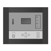
4 Detailed description of the control panel ............................................................................................................................ 6
5 Icons used .......................................................................................................................................................................... 7
5.1 Status icons ................................................................................................................................................................. 7
6 Main screen ....................................................................................................................................................................... 9
7 Shut-down warning .......................................................................................................................................................... 10
7.1 Description ................................................................................................................................................................. 10
7.2 Compressor element outlet temperature .................................................................................................................... 10
7.3 Dewpoint temperature ................................................................................................................................................ 11
8 Shut-down ........................................................................................................................................................................ 12
8.1 Description ................................................................................................................................................................. 12
8.2 Compressor element outlet temperature .................................................................................................................... 12
8.3 Motor overload ........................................................................................................................................................... 13
9 Service warning ............................................................................................................................................................... 14