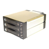
occurs the buzzer
alarms (default setting: 60°C and the
temperature LED turns red meanwhile
buzzer is alarming and LED is blinkin
).
press the Reset Switch to stop the alarm,
and LED goes off.
D.2--- D.4 (HD1〜HD3, Power SW and LED:
Power on, LED indicates Green. Oran
. (see
Picture E)
Picture E
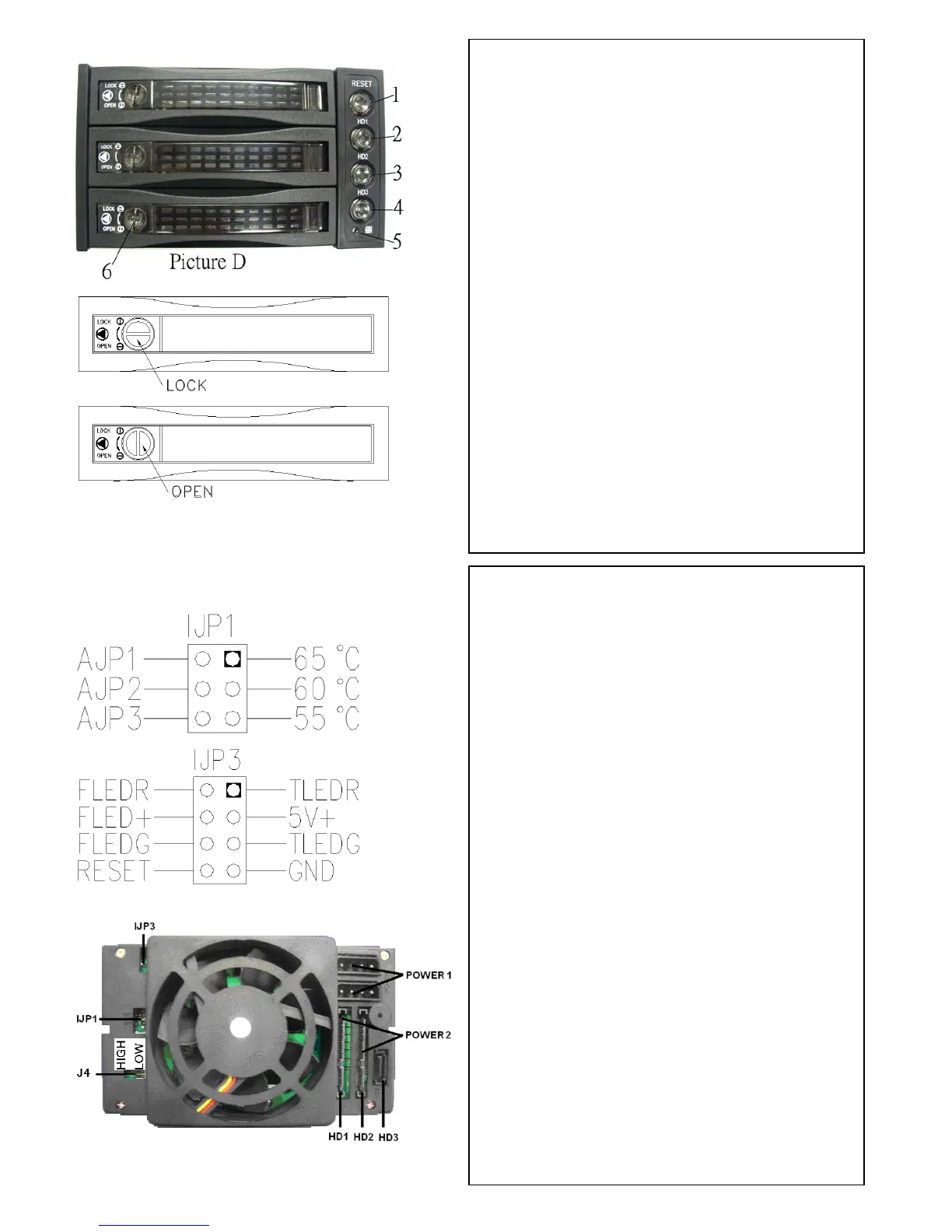
POWER1: 4pin Power connector
POWER2: 15pin Serial ATA Power
connector
HD1—HD3: 7pin Serial ATA Signal
con
in
ower
r.
can mix using 4pin and 15pin
r
ch for buzzer alarm and
ture detection (red)
ture detection (green)
J4: FAN RPM HIGH & LOW Optional
nector
If your power is not from SATA 15p
connector, please use the 4pin p
connector. The 4pin power will
automatically be converted to SATA powe
(Note: you
powers)
lJP1: Temperature setting jumpe
lJP3: Extension function jumper
FLEDR: Fan failure detection (red)
FLED+: Fan failure detection (+)
FLEDG: Fan failure detection (green)
RESET: Reset Swit
Overheating LED
TLEDR: Tempera
5V+: 5V Power
TLEDG:Tempera
GND:Grounded
---Rear View--- (see picture F)
Picture F
 Loading...