Do you have a question about the Chigo CMV-V64T9AD and is the answer not in the manual?
| Brand | Chigo |
|---|---|
| Model | CMV-V64T9AD |
| Category | Air Conditioner |
| Language | English |
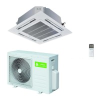
Identifies the specific DC Inverter Dual series models covered, such as CMV-50V9A-S and CMV-V64T9AD.
Details technical specifications like cooling/heating capacity, power input, and refrigerant type for various models.
Specifies the indoor and outdoor temperature/humidity conditions for performance testing as per ANSI/AHAM standards.
Outlines the acceptable upper and lower operating temperature ranges and voltage for cooling and heating.
Highlights energy efficiency, variable power output for comfort, and low consumption features of the DC inverter technology.
Details features like anti-corrosion condenser, cross-flow fan, round form, removable panel, and double-bend heat exchanger for performance and longevity.
Provides guidelines for preventing motor demagnetization, including peak current and discharge temperature limits.
Presents a reference chart showing the relationship between compressor operating frequency and condensing pressure.
Illustrates suction pressure variations against outdoor temperature for different indoor conditions.
Shows discharge pressure variations against outdoor temperature for different indoor conditions.
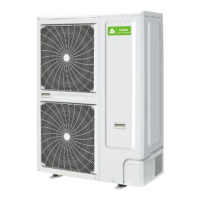
Provides detailed dimensional drawings for the outdoor units CMV-50V9A-S and CMV-V64T9AD.
Specifies the required mounting dimensions (codes A-E) for the outdoor units.
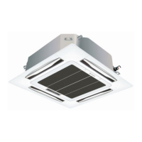
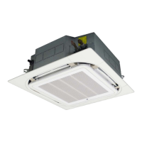
Details the body and mounting dimensions (codes A-F) for indoor units CMV-V25G9A-A and CMV-V32G9A-H.
Presents a visual breakdown of the outdoor unit's components for model CMV-50V9A-S with part numbers.
Shows a visual breakdown of the outdoor unit's components for model CMV-V64T9AD with part numbers.
Analyzes common indoor unit malfunctions, their causes, and troubleshooting steps for specific faults.
Lists and explains fault codes related to the outdoor unit's electrical control system and their troubleshooting.
Provides a consolidated analysis of common indoor and outdoor unit malfunctions with detailed reasons and solutions.
Details the cause and solution for communication faults between indoor and outdoor units (F1 code).
Explains troubleshooting steps for indoor temperature sensor failures, leading to F2 error codes.
Guides on diagnosing and resolving faults related to the indoor coil temperature sensor (F3 code).
Provides troubleshooting for indoor fan motor issues, identified by F4 error codes.
Outlines steps to diagnose and fix outdoor temperature sensor issues that trigger F6 codes.
Addresses communication errors between the wire controller and indoor PCB, resulting in FA fault codes.
Analyzes and provides solutions for large indoor input current issues indicated by P3 fault codes.
Describes troubleshooting for compressor discharge temperature exceeding limits, causing P4 errors.
Details how to address abnormal DC generatrix voltage in the outdoor unit, indicated by P7 fault codes.
Guides on resolving issues related to low refrigerant or reverse valve problems, signaled by P8 codes.
Explains troubleshooting for outdoor unit drive faults and compressor start failures, identified by FC codes.