Do you have a question about the Chigo KFR-35GW and is the answer not in the manual?
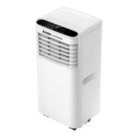
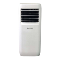
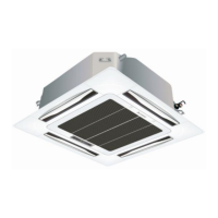
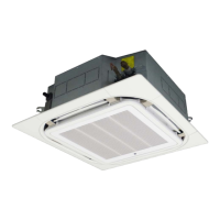
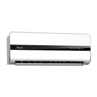
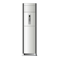
Describes specifications and models of indoor units.
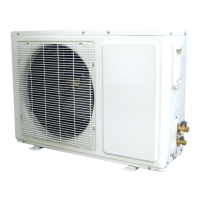
Describes specifications and models of outdoor units.
Details the coding structure and meaning of model names.
Essential safety instructions to prevent injury and damage during installation.
Important warnings related to installation practices and component usage.
Provides specific technical details for installation, including torque and pipe specs.
Lists components and their arrangement for indoor and outdoor units.
Illustrates the refrigerant flow and operational principles of the air conditioner.
Electrical schematic diagrams for various indoor unit models.
Electrical schematic diagrams for various outdoor unit models.
Schematic diagram for specific PCB models (38 section).
Schematic diagram for specific PCB models (65 Mitsubishi main chip).
Schematic diagrams for specific PCB models (85 section).
Schematic diagrams for compatible electrically controlled boards (18NV 85).
Schematic diagrams for Mitsubishi Jin dynasty 85 model motherboards.
Explains LED indicators and display functions for different panel types.
Describes operational logic and conditions for cooling mode.
Details operational logic and conditions for heating mode.
Explains intelligent defrosting logic and conditions in heating mode.
Describes the operation and logic for dehumidification mode.
Explains operation in ventilation mode for single cooling units.
Describes conditions and logic for automatic operation mode.
Explains the function of timer settings for unit operation.
Details the operation of the sleep mode and its indicator.
Explains the use of the physical execution key for operation and self-check.
Lists fault codes, LED indications, and their meanings for troubleshooting.
Troubleshooting steps for indoor temperature sensor errors.
Troubleshooting steps for indoor coil pipe temperature sensor errors.
Diagnostic flowchart for when the indoor fan motor fails to operate.
Troubleshooting flowchart for compressor operational issues.
General troubleshooting guide with flowcharts for unit malfunctions.
Diagnostic flowchart for when neither the indoor nor outdoor unit operates.
| Power Supply | 220-240V, 50Hz |
|---|---|
| Air Flow (Indoor) | 600 m³/h |
| Operating Temperature (Cooling) | 18-43 °C |
| Operating Temperature (Heating) | -7-24 °C |
| Cooling Capacity | 3.5 kW |
| Noise Level (Indoor) | 38 dB(A) |