Do you have a question about the Chigo KFR-51GW and is the answer not in the manual?
Identifies the manual as a service manual for CHIGO split wall-mounted air conditioners.
Advises reading the manual and contacting the service center if problems arise.
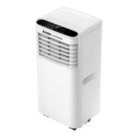
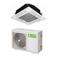
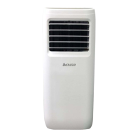
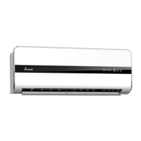
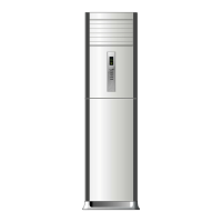
Lists and describes various indoor unit models with specifications.
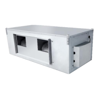
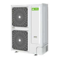
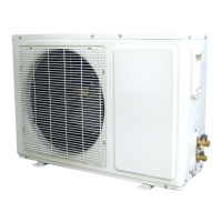
Details outdoor unit models, capacities, and dimensions.
Breaks down the alphanumeric model naming convention for air conditioners.
Outlines essential safety measures to follow before and during installation.
Provides critical warnings related to electrical safety and proper installation practices.
Lists precautions to avoid electric shock, fire, and explosion risks during installation.
Covers safe installation locations, grounding, and power cable handling.
Details safety guidelines for operating the unit, cleaning, and filter maintenance.
Provides cautions for installation, including refrigerant checks and unit placement.
Specifies torque values for wrench tightening during installation.
Details wire gauge requirements for power cord connections based on unit capacity.
Outlines maximum pipe lengths and elevation differences for different unit capacities.
Guides on selecting suitable locations for indoor unit installation.
Specifies minimum space needed around the unit for installation and maintenance.
Details the allowable height difference between indoor and outdoor units.
Illustrates required clearances around the outdoor unit for proper operation.
Instructions for securely mounting the wall plate for the indoor unit.
Details on drilling holes in the wall for pipe passage and drainage.
Guidance on installing the drain pipe for condensate water removal.
Steps for connecting pipes and wiring, and hanging the indoor unit.
Lists essential checks after installing the outdoor unit.
Procedures for connecting refrigerant pipes and purging air.
Detailed steps for using a vacuum pump to evacuate the system.
Specifies the amount of refrigerant to add based on pipe length.
Methods for checking refrigerant leakage after installation.
Procedures for connecting pipelines using quick coupler models.
Step-by-step guide for connecting pipelines on whole-unit quick coupler models.
Instructions for connecting the power cable to the unit.
Final steps for installation and initial system testing.
How to verify if the unit has been installed correctly.
Guidance on minimizing operational noise and its impact on surroundings.
Recommendations for periodic inspection and maintenance of the air conditioner.
Refers to separate files for explosion diagrams and spare parts lists.
Illustrates the refrigerant flow and working principle of the air conditioner.
Steps to check if the unit's display is functioning correctly.
Verifies if the outdoor unit is running as expected.
Assesses the normal operation of the compressor and related components.
Verifies the normal functioning of the indoor unit.
Provides circuit diagrams for indoor units of 38 series models.
Provides circuit diagrams for indoor units of 85 series models.
Circuit diagram for the CS-61H3A-P85AE2 indoor unit.
Circuit diagram for the CS-70H3A-T**AS indoor unit.
Circuit diagram for the KFR-70GW/X1c indoor unit.
Circuit diagrams for multiple outdoor unit models.
Detailed schematic diagram for the 38 series crystal color PCB.
Schematic diagram for the Mitsubishi main chip of the 65 model.
Schematic diagrams for 85 series models.
Electrically controlled schematic for the 18NV 85 model.
Explains the role of the PCB in controlling the air conditioner's functions.
Describes the meaning of different LED indicators on the display panel.
Details the operational logic for the cooling mode.
Details the operational logic for the heating mode.
Describes the intelligent defrosting mechanism and conditions.
Details defrost control logic managed by the outdoor PCB.
Information about the outdoor sensor used in defrosting.
Details operation in ventilation mode, applicable to single cooling units.
Explains the conditions and logic for the automatic running mode.
Covers time-on/time-off and sleep function controls.
Describes the use of the emergency key for unit operation.
Lists LED codes and their corresponding failures and solutions.
Diagnoses and resolves issues related to the indoor Tr sensor.
Diagnoses and resolves issues related to the indoor TP1 sensor.
| Brand | Chigo |
|---|---|
| Model | KFR-51GW |
| Category | Air Conditioner |
| Language | English |