2
H00701:07/01
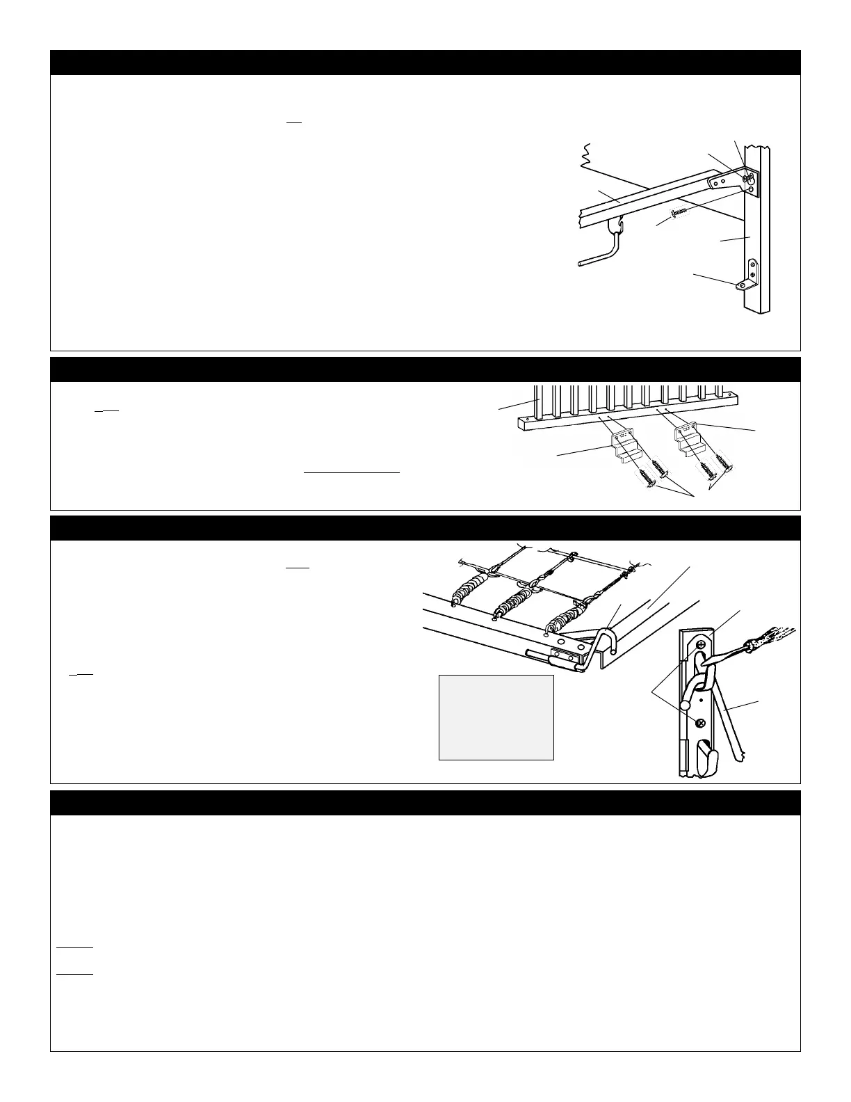
STEP 2 - DIAGRAM 2: INSTALL STABILIZER BARS.
STEP 3 - DIAGRAM 3: ATTACH G ATE S HOES TO DROPSIDES.
Position two Gate Shoes
CC
CC
C to lower rail
(inside)
of each Dropside
PP
PP
P as
shown. NOTE: Gate Shoe Patent No. will be visible when Gate Shoes
CC
CC
C are
mounted. Align Gate Shoes
CC
CC
C over predrilled lead holes on lower rail
(inside)
of Dropsides
PP
PP
P and affix with (8) Slotted/Phillips Wood Screws
EE
EE
E, two in
each Gate Shoe
CC
CC
C
.
Tighten Screws
EE
EE
E securely.
NOTE: When disassembling crib in the future, DO NOT REMOVE Gate
Shoes
CC
CC
C or any other hardware item attached with Slotted/Phillips
Wood Screws
EE
EE
E.
E
C
C
P
Locate Crib Spring
RR
RR
R,
(with plastic pouch factory attached)
, and the (4)
Spring Hangers
BB
BB
B, refer to Diagrams 4 and 5. NOTE: Be sure smooth side
of Crib Spring
RR
RR
R wire is placed upward as illustrated in Diagram 5. The
printing on the plastic pouch will be facing upward. Insert Spring Hangers
BB
BB
B into each bracket attached to frame of Crib Spring
RR
RR
R as shown. A light
blow with a hammer may be required to fully engage Spring Hangers
BB
BB
B
.
Carefully install Crib Spring
RR
RR
R by placing each of the 4 Spring Hangers
BB
BB
B
into a selected position in each of the (4) 4-Position Spring Hanger Brackets
DD
DD
D, mounted on Headboard
NN
NN
N and Footboard
OO
OO
O. See Diagrams 4 and
5. NOTE: The lip of the moulded plastic backer will allow the Spring Hanger
BB
BB
B to be placed with no difficulty. However, when you decide on another
placement of Crib Spring
RR
RR
R you will need to place your thumbnail, or a small
screwdriver, on the lip of the moulded plastic backer and hold down in order
to raise Spring Hanger
BB
BB
B from its present position. Follow this same
procedure when you decide to change Crib Spring
RR
RR
R to another of the four
positions.
B
STEP 4 - DIAGRAM 4: INSTALL SPRING H ANGERS & CRIB S PRING
CLOSE UPCLOSE UP
CLOSE UPCLOSE UP
CLOSE UP
VIEW VIEW
VIEW VIEW
VIEW
To remove Spring
Hanger
BB
BB
B press
down on lip with
thumbnail or screw-
driver and pull Spring
Hanger
BB
BB
B upward.
D
E
B
R
Top surface
STEP 5: INSTALL D ROPSIDES & CASTERS
Refer to Diagrams 2 and 5. You will need a total of (8) Slotted/Phillips Machine Screws
AA
AA
A along
with (2) Stabilizer Bars
JJ
JJ
J, Headboard
NN
NN
N, and Footboard
OO
OO
O
.
First, install a Machine Screw
AA
AA
A into each of the
top
receiving bushings in Headboard
NN
NN
N and Footboard
OO
OO
O at the areas for the attachment of Stabilizer Bars
JJ
JJ
J. Thread the screws in approximately (4)
revolutions into the receiving bushings - do not tighten at this time. Refer to Diagram 2.
Lay Footboard
OO
OO
O flat on a carpeted floor (to prevent scratching) with the attached hardware facing
up. Attach a Stabilizer Bar
JJ
JJ
J to Footboard
OO
OO
O by placing the keyhole
(top hole in each end of Stabilizer
Bar
JJ
JJ
J, over the extended Machine Screw
AA
AA
A. Install a Machine Screw
AA
AA
A in the lower receiving hole
in the end of the Stabilizer Bar
JJ
JJ
J and thread into the receiving bushing as shown in Diagram 2. Tighten
both Machine Screws
AA
AA
A securely to the Stabilizer Bar
JJ
JJ
J.
Carefully raise Footboard
OO
OO
O so that it is standing on its posts. The attached Stabilizer Bar
JJ
JJ
J can be
used to balance Footboard
OO
OO
O against.
Next, attach Headboard
NN
NN
N to the loose end of Stabilizer Bar
JJ
JJ
J. Place the keyhole on the loose end
of Stabilizer Bar
JJ
JJ
J over the extended Machine Screw
AA
AA
A in Headboard
NN
NN
N. Install a Machine Screw
AA
AA
A into the lower receiving hole in the end of Stabilizer Bar
JJ
JJ
J and thread it into the receiving bushing.
Tighten both Machine Screws
AA
AA
A securely.
Attach the other Stabilizer Bar
JJ
JJ
J to Headboard
NN
NN
N and Footboard
OO
OO
O using Machine Screws
AA
AA
A and
following the same process just described.
A
A
Extended
J
I
Factory
installed
Keyhole
O
Locate Crib Rods
KK
KK
K, Dropsides
PP
PP
P, Compression Springs
FF
FF
F, Bumper
Springs
GG
GG
G and the (4) remaining Slotted/Phillips Machine Screws
AA
AA
A.
Refer to Diagram 5.
Begin with either side of Headboard
NN
NN
N. Insert a Crib Rod
KK
KK
K downward
through the holes in the following sequence:
1.1.
1.1.
1. Top rail
(with plastic teething rail)
of Dropside
PP
PP
P,
(Note: gate shoes will be placed to inside),
2.2.
2.2.
2. L- bracket on 4-Position Spring Hanger Bracket
DD
DD
D,
Do Not include Compression Spring
FF
FF
F
at this time.
3.3.
3.3.
3. Bottom Rail of Dropside
PP
PP
P,
Do Not include Bumper Spring
GG
GG
G
at this time.
4.4.
4.4.
4. Hole in Angle Bracket
II
II
I.
Let the bottom end of Crib Rod
KK
KK
K rest on the floor. This will steady Dropside
PP
PP
P while you attach it's other end to Footboard
OO
OO
O.
Attach the other end of Dropside
PP
PP
P to Footboard
OO
OO
O by inserting a Crib
Rod
KK
KK
K downward through the holes in the following sequence:
1.1.
1.1.
1. Top rail
(with plastic teething rail)
of Dropside
PP
PP
P,
(Note: gate shoes will be placed to inside),
2.2.
2.2.
2. L- bracket on 4-Position Spring Hanger Bracket
DD
DD
D,
3.3.
3.3.
3. Compression Spring
GG
GG
G (small end up),
4.4.
4.4.
4. Bottom Rail of Dropside
PP
PP
P,
5.5.
5.5.
5. Bumper Spring
GG
GG
G,
6.6.
6.6.
6. Hole in Angle Bracket
II
II
I.
Return to Headboard
NN
NN
N to insert a Compression Spring
FF
FF
F and a Bumper
Spring
GG
GG
G. Raise Crib Rod
KK
KK
K out of hole in Angle Bracket
II
II
I and Bottom
Rail of Dropside
PP
PP
P. Lower Crib Rod
KK
KK
K downward through holes in the
following sequence:
1.1.
1.1.
1. Compression Spring
GG
GG
G (small end up),
2.2.
2.2.
2. Bottom Rail of Dropside
PP
PP
P,
3.3.
3.3.
3. Bumper Spring
GG
GG
G,
4.4.
4.4.
4. Hole in Angle Bracket
II
II
I. STEP 5 continued on Page 3.
 Loading...