The V31 is a wireless digital data link module designed for video, data, and RC (remote control) transmission, leveraging LTE wireless communication, adaptive OFDM, and MIMO technology. It facilitates communication between an airborne unit and a ground unit, supporting control of drones, UAVs, UGVs, and other devices.
Function Description:
The V31 system comprises an airborne unit and a ground unit. Once powered on and successfully connected (indicated by a constant signal light, typically within 30 seconds), the device operates normally with pre-configured parameters. It supports point-to-multipoint network communication, allowing the ground unit to act as a master and connect to up to 16 airborne slave units. Data transmission and reception are facilitated through LAN ports on the airborne units and a TTL interface on the ground unit.
The device offers several key functionalities:
- Video Transmission: Supports pull-streaming video acquisition via the LAN port, allowing connection to IPC devices and display on a PC using streaming software like VLC Media Player.
- Data Transmission: Provides serial port communication for flight control and ground station software, with configurable baud rates.
- RC Link: Enables remote control of aircraft, gimbals, and other devices through S-BUS ports.
- Fail-Safe Protection: Includes a remote control fail-safe protection setting, allowing users to store a fail-safe value that the airborne unit will output if SBUS data from the ground unit is lost for more than 3 seconds. This feature can be written, triggered, and turned off.
- Network Functionality: Supports network communication, with the ground unit acting as a master and up to 16 airborne units as slaves. Data can be transmitted via the TTL interface of the ground unit and received by the TTL interface of each airborne unit. Airborne units can also access other IP-connected devices (e.g., LAN cameras) via their network interface IP.
- USB Port Functionality: Incorporates a virtual network card function for video and data output, requiring a specific driver installation.
Important Technical Specifications:
- Power Supply: DC 7.4-30V (2s-6s lithium battery) for both airborne and ground units.
- Frequency Band: 800MHz and 1.4GHz (with options for 806-826MHz and 1427.9-1447.9MHz).
- RF Power: 2W, 5W (adjustable).
- Transmission Range:
- V31C: 5km grade (ground to ground)
- V31: 20km grade (air to ground)
- V31 Plus: 30km grade (air to ground)
- V31 Pro: 50km grade (air to ground)
- (All ranges are under LOS condition)
- S-BUS Ports: 2*S-BUS ports.
- Serial Port: 1*serial port (default: TTL; optional: RS232), full duplex, baud rate adjustable.
- Video Latency: 200-300ms.
- Bandwidth: 1.4-20M (configurable options: 1.4M/3M/5M/10M/20M).
- Video Input/Output: LAN (connecting IPC device/PC).
- Power Supply Interface: XT30.
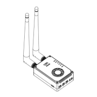
- Antenna: ZYJB antenna & fiber glass epoxy antenna.
- Dimensions: 80mm*56mm*25mm.
- Weight: 160g (excluding antenna).
- Operation Temperature: -20°C to +50°C.
- Default Configuration Parameters:
- User name: admin123
- Password: admin123
- LAN port IP: 192.168.168.12 (airborne unit); 192.168.168.11 (ground unit)
- Secret key: 88
- Wireless parameters: frequency: 1.4G/800MHz; frequency hopping mode: enabled; bandwidth: 20M
- Serial port parameters: baud rate: 115200; 8 data bits; 1 stop bit; no parity
Usage Features:
- Indicator Lights: Provide visual feedback on device status:
- TXD/RXD: Flashing indicates data transmitting/receiving; OFF indicates no data.
- TTL/RS232: Flashing indicates serial port data communication; OFF indicates no serial port data.
- SBUS 1/SBUS 2: Flashing indicates signal transmission; OFF indicates no signal transmission.
- LAN: Flashing indicates LAN port connected.
- Signal Strength (RS1, RS2, RS3): ON indicates strong signal (all three), moderate signal (RS1&RS2 ON), weak signal (RS1 ON); OFF or running horse lights indicate no connection.
- Bottom Noise Fault (S1, S2, S3 red): S1 flash (red) indicates main antenna poor bottom noise; S2 flash (red) indicates secondary antenna poor bottom noise.
- Frequency Check: Short press SET key (<3S) when power on: S3 ON (red) for 800MHz; S2, S3 ON (red) for 1.4GHz.
- Fail-Safe Protection Data Output: S1&S2&S3 sharp-flash indicates outputting fail-safe protection data.
- Serial Port Baud Rate Change: Press and hold SET key for ~3 seconds after power-on until RX and TX lights up. Briefly press SET to cycle through baud rates (9600, 19200, 38400, 57600, 115200bps), indicated by corresponding LED ON. Long press SET for ~2 seconds to save.
- LAN Port Operation: Connect airborne unit to IPC devices and ground unit to PC. Ensure PC's local connection IP is on the same network segment as the camera (e.g., 192.168.167.xxx).
- Module Configuration: Accessed via a web interface (e.g., 192.168.168.11) after setting PC's IP to the same network segment. Allows configuration of:
- Key Setting: Set secret key for communication (must be same for airborne and ground units).
- Master-Slave Setting: Not recommended to modify unless necessary.
- Wireless Setting: Modify frequency band, bandwidth, power, and frequency hopping. Ensure consistency between airborne and ground units.
- IP Address Change Management: Modify IP addresses (not recommended to change randomly; ensure ground and airborne units are on the same network segment).
- UP-DOWN Settings Management: Change uplink to downlink rate ratio (e.g., 1D4U for 1:4 downlink:uplink).
- Debug Interface: For fixed-frequency point output using AT commands (e.g., AT^DRPS).
- Bottom Noise Prompt Function: Active within 200 meters after link connection, suitable for pre-flight checks. Automatically closes beyond 200 meters. Test in LOS conditions for accuracy.
Maintenance Features:
- Firmware Version View: Connect the radio to a PC via USB cable, install a serial port debugging assistant, and power on the V31. The serial assistant will display the firmware version (e.g., <V31SX-1.0----V31SX-0.0.2----sysbaud: 115200>).
- Firmware Upgrading:
- Connect V31 to the computer using a TTL-to-USB cable (White-TX, Black-G, Green-RX).
- Long press the SET key to power on, release when RX and TX indicators are continuously ON.
- Open the upgrade software (BootLoader_2.0.6) within 1 minute.
- Click the refresh button to display device information.
- Open the correct firmware file (e.g., C:/Users/LINGHE/Desktop/V31RX_800M_1.0_1.0.1.bin).
- Click the play button to start the upgrade. The process is complete when "firmware write complete" is displayed.
- Troubleshooting:
- Weak Signal Strength: Check antenna connections, nearby high-powered devices, and adjust antenna distance/orientation.
- Unable to Stream Video: Ensure receiver IP address is on the same network segment as the IP camera.
- Garbled Transmitted Signal (SBUS/Serial Port): Verify consistent baud rates between remote control, receiver, and ground station software.
- Interference with Multiple Devices: Ensure each device set has a different ID (key) to avoid co-frequency interference.
- Significant Packet Loss/High Latency: Check antenna connections, module version consistency, wireless setup parameters, proper functioning of other devices/cables/interfaces, and streaming software settings.
Product Precautions:
- Always install antennas before powering up to prevent circuit damage.
- Ensure antennas are unobstructed, unbent, and away from large metal objects.
- Do not disassemble or modify the V31. Contact support for issues.
- Maintain proper distance between electronic devices to minimize electromagnetic interference.
- Verify secure wiring and proper component function before use.
- Check the environment for interference from other devices in the same frequency band.
- Do not use the USB port until the device is successfully connected to avoid abnormal signal strength indication.
- When changing the baud rate, ensure it is consistent across the airborne unit, ground unit, flight control, and other connected devices.