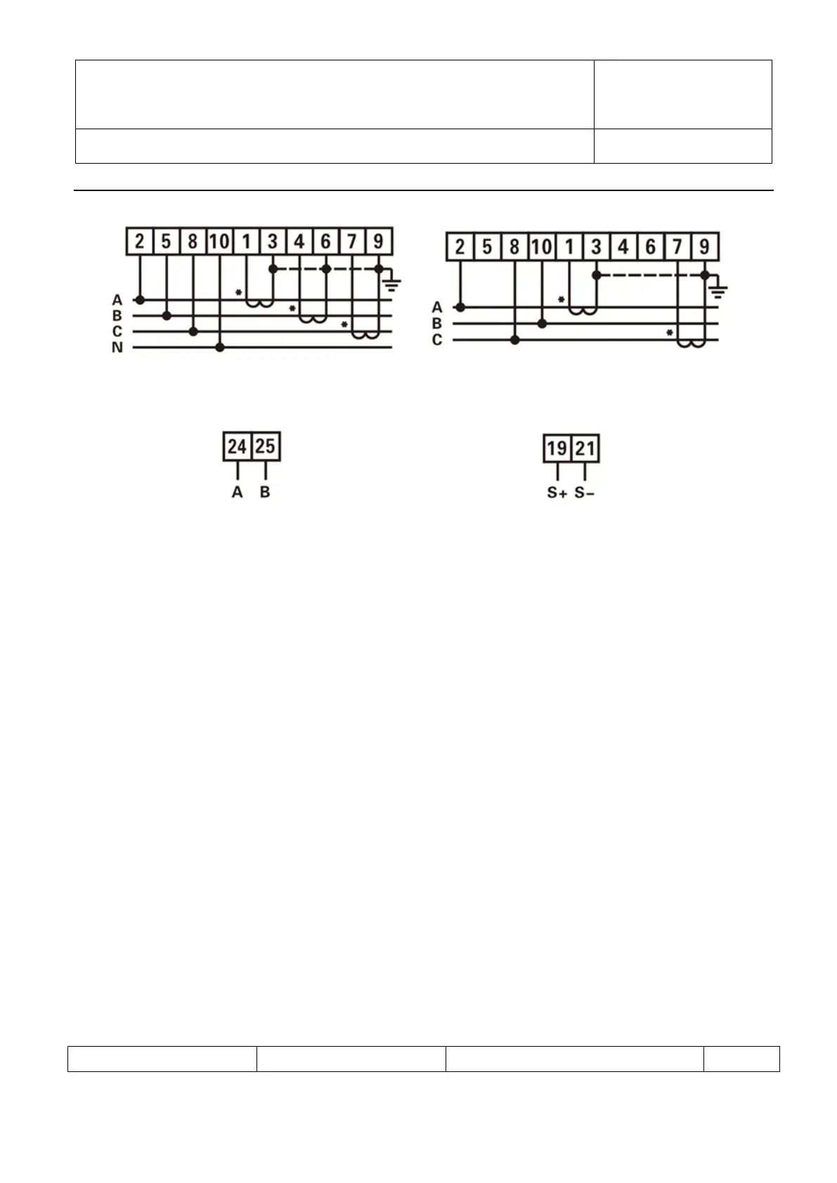
Figure 12 Figure 13
Three phase four wire: via current transformer Three phase three wire: via current transformer
Figure 14 Figure 15
RS485 Pulse output
Figure 16 Figure 17
◆ Voltage signal (only for connection via current transformer)
2-------UA (Phase A voltage input terminal) 5 -------UB (Phase B voltage input terminal)
8-------UC (Phase C voltage input terminal) 10------UN (Phase N voltage input terminal)
◆ Current signal:
1-------IA*(Phase A current input terminal) 3------IA (Phase A current output terminal)
4-------IB*(Phase B current input terminal) 6------IB (Phase B current output terminal)
7-------IC*( Phase C current input terminal) 9------IC(Phase C current output terminal)
◆ RS485 Communication wire
24-------A(RS485 Terminal A) 25-------B(RS485 Terminal B)
◆ Auxiliary function
19------ Active energy and reactive energy output high terminal
21------ Active energy and reactive energy output low terminal
NOTICE:In the Figure 12、13、14、15,the L1、L2、L3 correspond to Phase A、Phase B、Phase C
8.Diagnosis, analysis and elimination for common faults