07
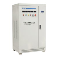
TNDZ、 TNSZ series pillar type AC automatic voltage regulators
7.6 Notes
7.6.1 You should understand the operating conditions of the voltage regulator before it is put into operation, and the
requirements provided in Section 3 should be met.
7.6.2 The input wiring of the three-phase voltage regulator must be connected strictly in accordance with the three-phase
four-wire system. The input must be connected to the neutral wire, otherwise the voltage regulator and the powered device will
be damaged.
7.6.3 The imbalance of input power supply voltage and load will lead to the imbalance of the output voltage.
7.6.4 During the operation of the voltage regulator under load, the load should be added step by step in case of power
recovery after power failure, otherwise the excessive impulse current will damage the voltage regulator.
8 Maintenance, Lifting and Storage Precautions
8.1 Maintenance: The maintenance cycle varies greatly depending on the environment in which it is used, but the
maximum period should not exceed six months. During maintenance, the switch at the front end of the voltage regulator
should be turned off. You must ensure that there is no voltage at the upper end of the power switch at the input end of the
voltage regulator. At the same time, the power switch at the input end should be turned off.
8.1.1 Thoroughly clean all parts of the voltage regulator to avoid dust and dirt, especially the electric brush, the coil surface
of the voltage regulator, the sliding guide rail of the electric brush and the transmission parts.
8.1.2 Apply appropriate amount of N320 gear oil to the mechanical transmission parts on a regular basis, such as the
reducer and the drive chain; it is recommended to replace the oil in the reducer every 3 months.
8.1.3 Replace the worn or damaged electric brush in time to ensure reliable contact. When the product is working, the
movement of the electric brush will cause a weak point spark in the contact area. In case of large spark, cut off the power for
maintenance and clean the voltage regulator according to 8.1.1 of the maintenance requirements. If there is a gap between the
electric brush and the coil, put the 0# sandpaper between the electric brush and the coil and pull it up and down to ensure the
reliable contact between the electric brush and the cylindrical slide rail.
8.1.4 Repair or replace the broken-down or damaged components in time.
8.1.5 For the maintenance of the control motor, the wiring should be strictly consistent with the regulations and a wrong
phase sequence of the motor is strictly prohibited. After maintenance, perform the commissioning according
to 7.4 and the put the product into operation again after successful commissioning.
8.2 Lifting and storage period precautions
8.2.1 The product should be packaged and stored indoors. The room should be well-ventilated, dry, and free of vibration
and corrosive gas (liquid).
8.2.2 This product cannot be hoisted and can only be handled by forklift. Keep it dry and upright during handling.
9
Analysis and Troubleshooting of Common Faults
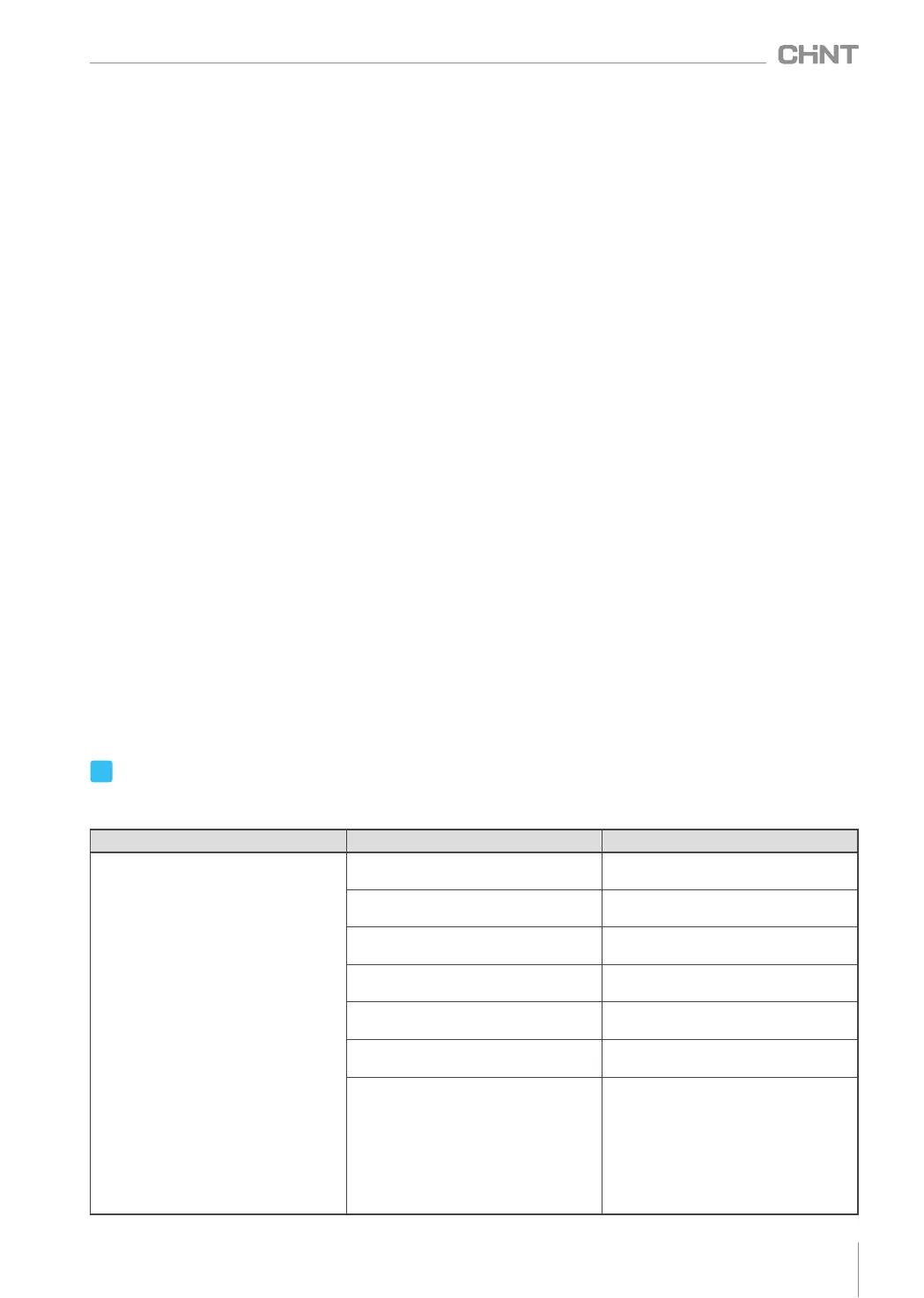
Table 3 Analysis and Troubleshooting of Common Faults
Symptons
Cause analysis
Troubleshooting method
The voltage regulator fails to start
after power connection.
Input power phase loss
Product is not connected to
the neutral wire
Mains button and voltage stabilization
button failure
Open circuit of contactor coil leads to
failure of pull-in
Fuse fault
Poor contact of control circuit
Check if the input power supply is
normal or has phase loss
Connected to the neutral wire
Replace the buttons
Replace the contactor coil
Replace with the fuse of the same
specification
Check if all connectors are securely
connected
Travel protection caused by low input
power voltage or out of control power
phase sequence
Check whether the brush plate slides
to the bottom of the voltage regulating
coil and causes the travel switch to be
disconnected. Adjust the reducer.
Move the brush plate to the middle
position of the voltage regulating coil
and restart the voltage regulator.
(TNSZ-150 or above)
 Loading...