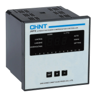
The JKF8 Series Smart Low-Voltage Reactive Power Compensation Controller is designed for use in low-voltage power distribution systems to automatically compensate for reactive power. It operates by compounding the control of physical variables, specifically reactive power and power factor, to facilitate automatic capacitor switching, improve power factor, and reduce reactive power loss in the line. The controller is designed for ease of operation, reliability, and possesses strong anti-interference capabilities. It complies with the JB/T9663 standard and is capable of accurately displaying the grid power factor even in harmonic environments.
Function Description
The controller's primary function is to maintain an optimal power factor by automatically adding or removing capacitor banks. Upon power-on, the device displays "CAL" and enters an auto-operating status after 5 seconds. If the input current meets the minimum requirement (greater than 150mA), the controller will display the measured grid power factor (COSΦ).
In full automatic setup mode, the controller initiates a "self-learning process." During this process, it compares a predefined "power factor value" with the current power distribution system's conditions. It then automatically adds capacitors to improve the power factor. Simultaneously, the controller records the values of the connected capacitor banks and uses the smallest capacitor bank's capacity as the reactive adding threshold.
Regardless of whether it's in automatic or manual parameter setup mode, the controller continuously compares the measured inductive reactive power demand with the F-1 reactive power threshold (Qs). If the inductive reactive power demand exceeds this adding threshold, a lagging indicator will begin flashing. After a set delay, capacitors are added level by level until the grid reactive power demand falls below the reactive power threshold Qs, and the power factor does not exceed the target power factor. Conversely, when the power factor of the grid exceeds the target power factor, a leading indicator will flash, and the system will automatically remove capacitor banks in operation, level by level, within 5 seconds.
The controller also incorporates several protective functions:
- Undervoltage protection: Automatically removes capacitor banks in operation level by level (within 5 seconds) when the grid voltage drops below 0.78UN, displaying the voltage value.
- Overvoltage protection: Automatically removes capacitor banks in operation level by level (within 5 seconds) when the grid voltage exceeds the overvoltage threshold, displaying the voltage value.
- Undercurrent protection: Automatically removes capacitor banks in operation level by level (within 5 seconds) and locks up capacitor adding when the secondary signal of the current transformer is lower than 150mA.
- Overcurrent alarm: Triggers an alarm when the sampling current exceeds 6.0A.
- Discharge delay protection: Implements a switching lock-up time of 3 minutes for the same group of capacitors.
- Circular self-test function: Provides a self-test feature for factory testing of the capacitor screen.
Usage Features
The JKF8 Series controller offers both full automatic and manual setup modes, providing flexibility for different system conditions and user preferences.
Full Automatic Setup Mode:
In this mode, extensive setup is not required beyond correct wiring. Users only need to correctly set the current transformer ratio (F-6). The system will then automatically display true values for total current, reactive power, and active power. This mode is designed to be user-friendly, allowing for quick deployment without complex configurations. The controller's self-learning capability simplifies the process of optimizing power factor compensation.
Manual Setup Mode:
This mode is intended for professional technicians who need to configure the system according to specific conditions. In manual setup mode, users must correctly set the current transformer ratio when first starting the device. This allows for fine-tuning of parameters such as adding threshold, target power factor, switching delay, and overvoltage threshold.
Parameter Setup and Operation:
- Threshold setup mode (F-0): Allows selection between full automatic (1) and manual (0) setup.
- Adding threshold (F-1): In manual mode, users can set the reactive power threshold for adding capacitors. This parameter is automatically determined in full automatic mode.
- Target power factor (F-2): Continuously adjustable from 0.85 to -0.95, allowing users to define the desired power factor. A negative value indicates a capacitive system.
- Switching delay (F-3): Sets the delay time before switching operations, adjustable from 5 to 120 seconds.
- Overvoltage (F-4): Configures the overvoltage threshold, providing protection against high voltage conditions.
- Number of control circuits (F-5): Specifies the number of capacitor control circuits available, either 1-6 or 1-12.
- Current sampling transformer ratio (F-6): Sets the ratio for the external sampling current transformer, crucial for accurate current measurements.
Operating the Controller:
- Entering Manual Mode: From automatic mode, press and hold the "SET menu" key for 3 seconds.
- Adding/Removing Capacitors (Manual Mode): Use the "+" key to add a group of capacitors and the "-" key to remove a group.
- Circular Self-Testing: From automatic mode, press and hold the "SET menu" key for 10 seconds until the decimal point flashes. It is important to disconnect the capacitor before performing this test.
- Changing Set Parameters: In manual mode, press and hold "SET menu" for 3 seconds to enter the parameter setup menu. Continue pressing "SET menu" to cycle through parameters. Use "+" or "-" to adjust values. Hold "SET menu" for 3 seconds to exit and save changes. If no key is pressed for 40 seconds in setup mode, the system will automatically revert to automatic mode.
- Dynamic Parameter Adjustment Display: In automatic mode, press "+" to cycle through dynamic parameter codes (Current, Voltage, Reactive Power, Active Power), then press "-" to view the corresponding values. Press "SET (menu)" to return to the main display (power factor COSΦ).
Installation:
The controller features a fire-retardant plastic case and a digital display. It is designed for embedded installation, similar to 42L series products. The installation procedure involves embedding the controller into a panel hole, then pushing mounting parts into the upper and lower slots, and tightening screws to secure it. Proper wiring involves connecting "US1" and "US2" to sampling voltage, "IS1" and "IS2" to sampling current from the total load current transformer, and "COM" to the relay common terminal for output control. External fuses (FU1-3) are required for protection.
Maintenance Features
Regular maintenance ensures the optimal performance and longevity of the JKF8 Series controller.
Daily Maintenance:
- Regular Status Checks: Users should regularly check the operating status of the controller. Typically, the displayed power factor should not exceed 0.92 and should remain relatively stable.
- Undercurrent Alarm Handling: If the sampling current is less than 200mA or an undercurrent alarm is displayed, it can be difficult to ascertain normal operation, as the power factor may be positive or negative, and the display status could be leading or lagging. In such cases, it is recommended to conduct motor load commissioning to verify the controller's functionality.
- Monitoring Power Factor and Current: As motor load increases, the power factor value will decrease, and the controller will display a lagging status. As capacitors are automatically added, the power factor should gradually increase, and the total current of the cabinet should decrease. Users should record these values in real-time for monitoring.
- Manual Capacitor Removal: Before disconnecting the power supply of the cabinet, use the universal change-over switch on the controller or the cabinet to manually remove any capacitor banks currently in operation.
- Current Transformer Handling: When removing or replacing the JKF8 controller, short-circuit the secondary side of the sampling current transformer to prevent an open circuit. Remember to remove the short-circuit line after reinstalling the controller.
Troubleshooting:
The manual provides a comprehensive guide for analyzing and troubleshooting common faults, including:
- Undercurrent display ("=1"): Possible causes include sampling current below 150mA, open secondary circuit of the current transformer, or a fault in the current transformer or controller. Solutions involve checking the secondary circuit and replacing the controller if necessary.
- Overcurrent display ("=0"): Indicates that the current transformer sampling current exceeds 6.0A, suggesting an incorrect current transformer ratio. The solution is to select a CT with a primary current larger than the load current.
- Undervoltage/Overvoltage alarm ("EU" or voltage value): May be due to undervoltage or overvoltage conditions or a product fault. Solutions include testing the voltage before adjusting the overvoltage threshold or replacing the product if the increase is invalid.
- Fluctuating power factor/leading and lagging indicator switching: Often caused by low load, frequent load changes (e.g., from welding machines), or an unstable electrical load. Solutions include turning on motor load, selecting dynamic reactive power compensation equipment, or choosing a controller with non-isometric optimal switching.
- Power factor remaining unchanged after adding capacitors: This could be due to incorrect installation of the current transformer, where the primary current is not included in the cabinet. The solution involves ensuring the primary line of the cabinet is connected after the sampling transformer.
- Controller always displaying leading/negative power factor, no automatic operation: Possible causes include wrong sampling phase sequence or harmonic interference from equipment like frequency converters. Solutions involve determining the correct sampling phase sequence and selecting a controller with stronger anti-harmonic interference capability.
- Frequent capacitor switching: May result from a fast-changing load current, a short delay time, a low target power factor, or a low reactive power threshold. Solutions include increasing the delay time, target power factor, or reactive power threshold.
- Low power factor (below 0.90) with no automatic capacitor addition: This can happen if the load is relatively low, the required reactive power (Qs) is smaller than the F-1 reactive power threshold, or the transformer ratio is too small. Recommendations include using capacitors with smaller capacity or correcting the transformer ratio.
- Garbage characters on display or controller crash: Often caused by abnormalities like lightning strikes or electromagnetic interference. The suggested solution is to disconnect power and restart the device; if the problem persists, replace the product.