3.1 Main Features, Outline and Installation Dimensions
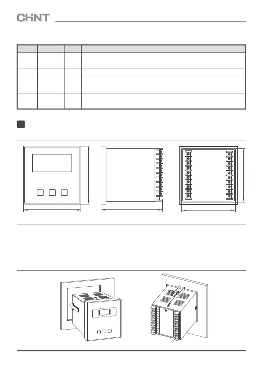
Figure 1 Outline dimensions of the product
The product is equipped with fire retardant plastic case and digital display. The installation method
of the product is the same as 42L series product. The outline dimensions of the product is 120mm×120
mm×130mm, the installation perforating dimension of the product 113 mm×113mm, the embedding
depth 116 mm.
3.2 Installation Procedure, Method and Product Wiring Diagram
3.2.1 Assembly and fixing of the controller
Figure 2 Product installation and fixing
Table 2 Description of dynamic parameters
Code
Definitions
Unit
Description
I Current A
Use approximate value when measured value exceeds display range, for
example: displays E13 for 1260A.
U
Voltage
V
Displays measured voltage
Q
Reactive
power
kvar
Use approximate value when measured value exceeds display range, for
example: displays E14 for1360 Kvar
P
Active
power
kW
Use approximate value when measured value exceeds display range, for
example: displays E14 for1360 Kvar
3
Installation
(120±2)mm
(120±2)mm
(130±2)mm
(109±1)mm
(109±1)mm
SET
+
-
JKF8 SeriesSmart Low-Voltage Reactive Power Compensation Controller
03