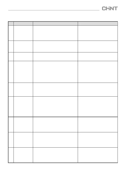
Table 5 Analysis and troubleshooting of faults
No.
Faults
Cause analysis
Solutions
1
Load equipment is
turned on, but the
controller still
displays
undercurrent “≡1”
1. The sampling current is smaller than
150mA or the secondary circuit of the
current transformer is open;
2. Fault exists in the current transformer
or the controller.
1. Check if the secondar y circuit of the
sampling current transformer is open;
2. If the measured IS1 and IS2 sampling
currents are bigger than 200mA,
replace the controller.
2
Sometimes the
controller
displays“≡0”
Current transformer sampling current is
bigger than 6.0A, which means the
selected sampling current transformer
ratio is too small.
Select CT based on the primary current
of current transformer is larger than
load current.
3
Controller always
displays “≡U”
or voltage value
1. Undervoltage or over voltage alarm,
display this code;
2. Product fault
Test voltage before increasing set
overvoltage threshold. If the increase
is invalid, replace the product.
4
The displayed
power factor keeps
changing, or the
leading and
lagging indicator
keep switching.
1. Load is relatively low and sampling
current is smaller than 200mA;
2. Caused by frequent load change,
such as electric welding machine,
spot-welder, rolling mill, pressing machine,
hauling equipment;
3. Electrical load is not stable; transformer
load rate is relatively low.
1. Turn on motor load and observe the
display of the controller;
2. Select dynamic reactive power
compensation equipment for fast
changing load;3. Select controller
that uses non-isometric optimal
switching, such as NWK1-GR liquid
cr ystal controller.
5
Af ter adding
capacitors, the
power factor
remains almost
the same.
The installation position of the current
transformer is wrong; the primary current
is not included in the cabinet.
Take total current: sampling current
=load current + capacitor current,
which means the primar y line of the
cabinet is connected after the
sampling transformer.
6
No matter what
load, the controller
always displays
leading, the power
factor is negative,
and the system
does not operate
automatically.
1. Wrong sampling phase sequence, such
as phase A for current, and phase AB for
voltage;
2. There is equipment such as frequency
converter or rectifier installed at load
end, which causes harmonic interference.
1. Determine sampling phase
sequence according to 7.3.4;
2. Select NWK1-GR liquid crystal
controller with stronger anti-
harmonic interference capability.
7
Capacitor
switching is too
frequent
1. Fast change of load current, the set
delay time is shorter than 10s;
2. The set target power factor is too low;
3. The set reactive power threshold is
too low.
1. The set delay time is longer than
30s;
2. Increase target power factor;
3. Increase reactive power threshold
properly.
8
The displayed
power factor is
lower than 0.90,
but no capacitor
is added
automatically.
1. Load is relatively low, the required
reactive power Qs is smaller than set
value of F-1 reactive power threshold;
2. The set transformer ratio is too small.
1. Recommend to replace with 2
groups of capacitors with smaller
capacity;
2. Set transformer ratio correctly;
9
The controller
displays garbage
characters or the
controller is
crashed.
1. Abnormalities such as lightning strike;
2. Electromagnetic interference。
Disconnect the power and restart the
machine. If the problem occurs
repeatedly, replace the product.
JKF8 SeriesSmart Low-Voltage Reactive Power Compensation Controller
08
 Loading...