6
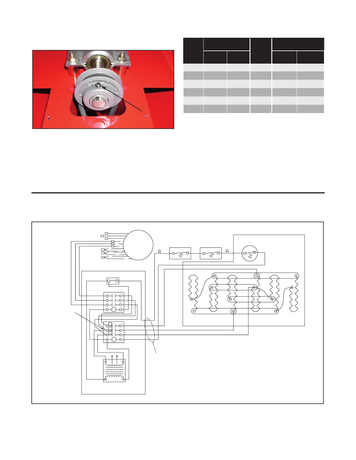
Wiring Diagrams
SDRA 30kW, 480V, 3PH
Side of Contactor to
Auxillary Terminals
Blk/Red
or Grey
Blk
Transformer
Control Enclosure
Blk
Wht
Run these Wires
Through 1" Conduit
Contactor
Motor Relay
Toggle Switch
L1
L2
L3
Motor
P4
P5
P6
T3
T1
T2
T9
T8
T7
T4
T6
T5
Inlet
Thermostat
Outlet
Thermostat
Cutout
12
1
Heater
10
Heater Terminal Box
4
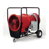
7. Loosen the set screw on the fan pulley or motor pulley.
Fig. 3 shows the construction of the fan pulley, the motor
pulley is the same construction.
Fan belt tension
adjusting bolts
Figure 3
8. Rotate the front half of the pulley clockwise until it bot-
toms, then rotate counter clockwise until the set screw
aligns with the flat in the threaded half of the pulley. The
pulley is now in position for adjustment. See Table 1 for
the number of turns out. Tip: Leave allen wrench in set
screw and use free hand to fold fan blade.
Table B
Fan
RPM
No. of turns from
full closed
Fan
RPM
No. of turns from full
closed
Motor
Pulley
Fan
Pulley
Motor
Pulley
Fan
Pulley
1500 3 1-1/2 1950 1-1/2 3
1600 2-1/2 1-1/2 2000 1-1/2 3-1/2
1650 2 1-1/2 2100 1-1/2 4
1725 1-1/2 1-1/2 2200 1-1/2 4-1/2
1800 1 1-1/2 2300 1 4-1/2
1850 1/2 1-1/2
9. Retighten set screw, use of thread locking compound is
recommended.
10. Adjust fan belt tension, see Fig. 2. A 1/2” of belt deflection
is recommended. Tighten lock nuts.
11. Tighten the 3/8” bolts, see Fig. 1
12. Rotate fan blade to make sure the fan belt does not rub.
13. Reinstall top belt cover, grille and lower belt cover. Tip: In-
stalling the grille before installing the lower cover makes
it easier to access the two lower grille bolts.
 Loading...