IMPO
RTANT NOTES:
Air in the heater may cause the elements to burn out. If the water lines are drained,
allowing air into the heater, be sure to follow the following start-up procedure:
1. Turn off electrical supply – open circuit breaker.
2. Turn on water supply.
3. Expel all air from lines and heater.
4. Turn on electrical power supply – close circuit breaker.
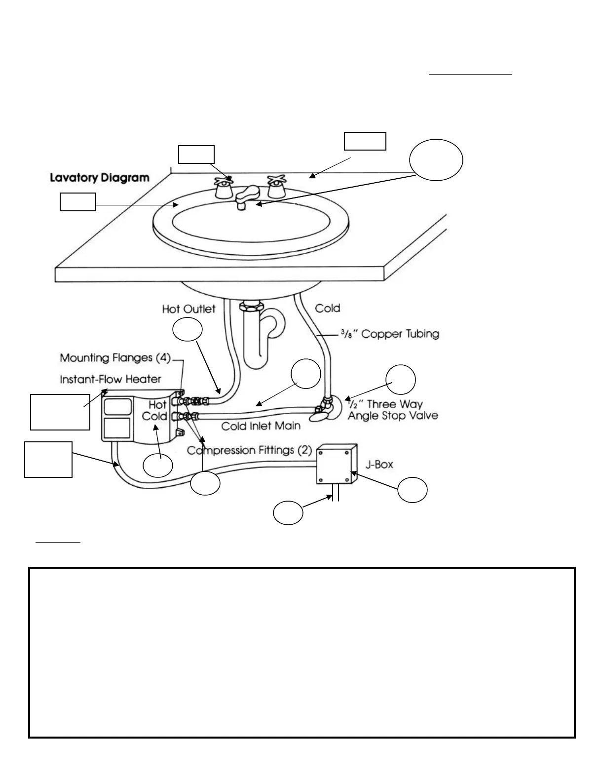
FIGURE 1 HEATER INSTALLATION
Faucet flow controls must be attached to the faucet to allow the water heating system to operate more effectively
(See Fig. 2, pg. 3 for installation).
Item Part No. Names Qty Description
1. SR-_ _L Chronomite Instant-Flow SR Heater 1 Models shown in Table 1
2. Electrical junction box
3. Electrical conduit ½” conduit, length as required
4. Electrical wire Electrical Wire
5. Dual outlet angle valve 1 ½” FPx7/16” comp.x3/8 comp., Brass
Craft P/N R2701R-RGH
6. Fitting (supplied) 2 3/8” comp x ¼”MP
7. Copper or flex tubing 1 3/8”OD, 5” long (keep short)
8. Copper or flex tubing 3/8” OD, length as required (keep short)
9. L-412 Faucet flow control, dual thread 1 Supplied with Low Flow Heater
OR (see figure #2) SR-15L, SR-20L, SR-30L
10. LP-412 Faucet flow control, dual thread 1 Supplied with Low Flow Heater
Hot
Sin
Mounting
Flange
Cold
#1
#2
#3
Conduit
#5
#6
#7
#9 , #10
#4
#8
Downloaded from www.GadgetsGo.com, Authorized Chronomite Distributor