Do you have a question about the Chronomite SR-40 and is the answer not in the manual?
Details model numbers, wattage, voltage, breaker size, dimensions, and installation overview.
Essential safety precautions and steps before beginning the installation process.
Covers electrical access, mounting, plumbing connections, and wiring.
How to activate the flow switch and adjust water temperature.
Explains the internal mechanism of heating water as it flows.
Details flow control requirements and available models for optimal operation.
Addresses problems like low power, voltage, and flow rate issues.
Guidance on water supply, freezing prevention, and draining the unit.
Information on the factory warranty coverage and terms.
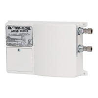
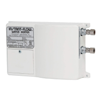
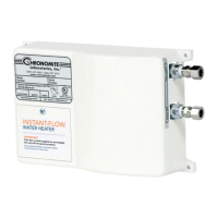
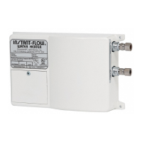
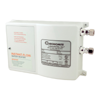
The Chronomite Instant-Flow SR Water Heater is an advanced, compact device designed to provide hot water on demand. This system eliminates the need for a traditional hot water tank, heating water instantly as it flows through the unit. Its primary function is to deliver hot water efficiently, reducing energy waste by only activating when hot water is requested.
The Instant-Flow SR Water Heater operates on a simple yet effective principle: water flows through a series of ingeniously designed coils housed within a durable cast alloy casing. When a hot water fixture is activated, a unique power switch automatically applies electrical current to these coils, heating the water as it passes through. This "instant-flow" mechanism ensures that hot water is available immediately, without the delay associated with tank-style heaters. When the hot water fixture is turned off, the electrical current to the coils is automatically cut, preventing continuous energy consumption. This on-demand heating not only provides convenience but also contributes to significant energy savings, as the unit does not continuously heat and store water.
The device is designed to activate when the water flow rate reaches one gallon per minute (GPM) and deactivates when the flow rate drops to 0.65 GPM. It's important to note that operating the heater at the minimum deactivation flow rate of 0.65 GPM is not advisable for optimal performance. The system is capable of delivering water at a maximum operating temperature of 140°F. The temperature of the hot water can be influenced by the flow rate; increasing the flow rate will result in cooler water. For users with two-handle faucets, cold water can be mixed with the hot water, similar to a conventional plumbing system, to achieve the desired temperature.
The Instant-Flow SR Water Heater is designed for straightforward installation and user-friendly operation. It is crucial to mount the unit horizontally against a wall, ensuring that the silver label is correctly oriented. This horizontal mounting is essential to prevent the heating elements from burning out. The plumbing connections utilize standard 1/4" NPT pipe threads for both cold water inlet and hot water outlet, and compression fittings are supplied for ease of installation. It is important not to apply heat to these fittings during installation.
Before initial use, or if the water lines have been drained, a specific start-up procedure must be followed to prevent air from entering the heater and potentially damaging the elements. This involves turning off the electrical supply, turning on the water supply, expelling all air from the lines and the heater, and then turning on the electrical power supply. Running water through the unit to expel air bubbles and checking for leaks at all fitting joints is a critical step during installation.
A key feature for optimal performance is the use of a faucet flow control. These controls, such as the A-412 (Dual) or A-910VR (Female) models, are designed to be attached to the faucet to regulate the water flow, allowing the heating system to operate more effectively. These flow controls are chrome-plated with brass housings and are adaptable to various thread configurations. Failure to install the faucet flow control as specified can lead to unsatisfactory operation of the heater.
The unit requires a minimum pressure of 25 PSI and can handle a maximum of 150 PSI (tested up to 300 PSI). A pressure relief valve is generally not needed unless mandated by local codes. The compact dimensions and lightweight design of the heater make it suitable for various installation locations, particularly where space is limited.
The Instant-Flow SR Water Heater is engineered for durability and reliability, with minimal user-serviceable parts. Regular maintenance primarily involves periodic inspection of the supply lines, connections, and the heater itself for any signs of moisture, corrosion, or other potential preventable problems. This proactive approach helps ensure the longevity and efficient operation of the unit.
In the event of a malfunction or if the heater does not provide hot water as expected, a troubleshooting guide is provided. This guide outlines several checks, including verifying the voltage supply to the heater using a voltage meter, checking the amperage draw with an Amperage Probe, and ensuring the shut-off valve is 100% open to allow full water pressure. The length of the pipe run from the heater to the point of use can also affect temperature increase, with a recommended distance of no more than 12-18 inches.
Proper flow rate control is essential for maintaining the desired temperature increase. If the unit is installed in a location subject to freezing temperatures, it must be drained and stored to prevent damage. This involves disconnecting the inlet/outlet compression fittings and blowing air through one side of the heater to assist in complete drainage. Failure to remove all water can lead to freezing and cracking of the unit.
For any issues that cannot be resolved through the troubleshooting guide, the manufacturer recommends returning the unit to the factory for repair or replacement, as it contains no internal user-serviceable parts. The product is backed by an exclusive 12-month warranty, guaranteeing it to be free from defects in material and workmanship from the date of purchase, provided it is installed according to the manufacturer's instructions. This warranty covers repair or exchange of defective parts at the factory, F.O.B. City of Industry, California.
| Voltage | 240 V |
|---|---|
| Flow Rate | 0.5 GPM |
| Wattage | 4000 W |
| Amperage | 16.7 A |
| Maximum Flow Rate | 0.5 GPM |
| Water Connection | 1/2" NPT |
| Type | Electric Tankless Water Heater |
| Power Rating | 4.0 kW |
| Temperature Range | 80°F to 140°F |
| Material | Copper |