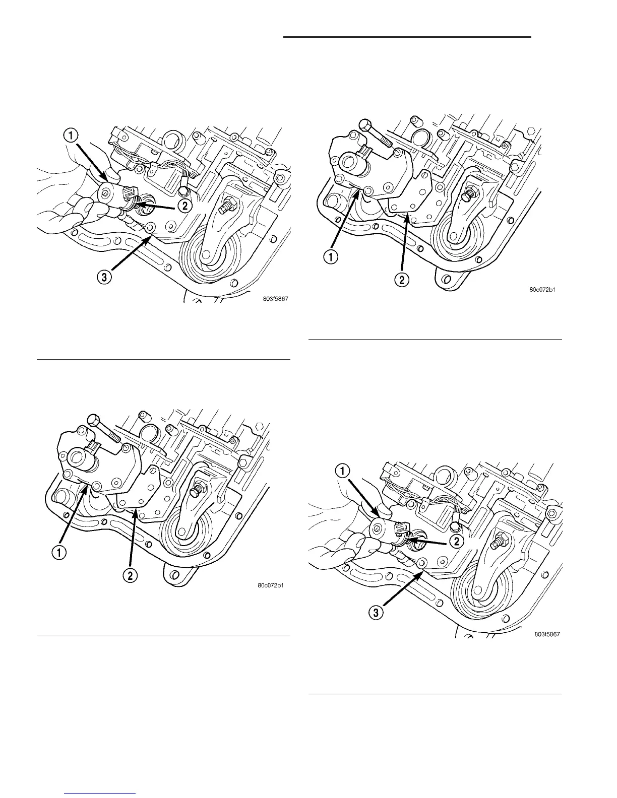
(6) Pull solenoid from governor body (Fig. 80).
(7) Pull pressure sensor from governor body.
(8) Remove bolts holding governor body to valve
body.
(9) Separate governor body from valve body (Fig.
81).
(10) Remove governor body gasket.
INSTALLATION
Before installing the pressure sensor and solenoid
in the governor body, replace o-ring seals, clean the
gasket surfaces and replace gasket.
(1) Place gasket in position on back of governor
body (Fig. 82).
(2) Place governor body in position on valve body.
(3) Install bolts to hold governor body to valve
body.
(4) Lubricate o-ring on pressure sensor with trans-
mission fluid.
(5) Align pressure sensor to bore in governor body.
(6) Push pressure sensor into governor body.
(7) Lubricate o-ring, on pressure solenoid, with
transmission fluid.
(8) Align pressure solenoid to bore in governor
body (Fig. 83).
(9) Push solenoid into governor body.
Fig. 80 Pressure Solenoid and O-ring
1 - PRESSURE SOLENOID
2 - O-RING
3 - GOVERNOR
Fig. 81 Governor Body and Gasket
1 - GOVERNOR BODY
2 - GASKET
Fig. 82 Governor Body and Gasket
1 - GOVERNOR BODY
2 - GASKET
Fig. 83 Pressure Solenoid and O-ring
1 - PRESSURE SOLENOID
2 - O-RING
3 - GOVERNOR
21 - 200 AUTOMATIC TRANSMISSION - 48RE DR
ELECTRONIC GOVERNOR (Continued)
 Loading...