Do you have a question about the Ciara Orion HF-210 and is the answer not in the manual?
Precautions for preventing electrical hazards.
Guidelines for safe operation and handling of the system.
Detailed specifications for the ORION HF210 server.
Technical details of the motherboard components and features.
Highlights key technologies and exclusive features like DIGI+ Power, TPU, EPU.
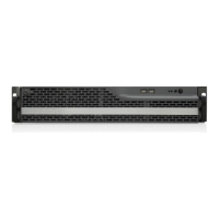
Provides an overview of the server chassis and its external parts.
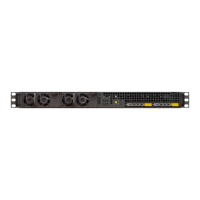
Details the front panel interface, controls, and indicators.
Explains rear panel connectivity and I/O interfaces.
Illustrates motherboard layout, PCI extension slots, and RAM DIMM slots.
Covers onboard switches and understanding the BIOS setup program.
Guide to entering and navigating the BIOS setup utility.
Details Main, Advanced, Monitor, Boot, Tools, and Exit menus.
Information on ASUS EZ Flash, CrashFree BIOS, BIOS Updater, and Server Mgmt.
Details specifications and features of the ASMB7-iKVM.
Information on ASUS System Web-based Management software.
Covers memory upgrade and testing procedures.
Steps for installing and removing DIMM modules.
How to use MemOK! for memory compatibility testing.
Procedures for replacing disks and fans.
Explains the function of DIAG, EPU, TPU, and Q-Code LEDs.
Status indicators for key components during POST.
Details the 2-digit Q-Code display for system status.
Covers CPU, DIMM, BMC, and CATERR warning LEDs.