Do you have a question about the CIAT FLOWAY CLASSIC RHE and is the answer not in the manual?
Information on device usage by persons and qualified personnel.
Overview of the control PLC's function and connectivity.
Details of PLC analogue and on/off inputs/outputs.
Detailed list of PLC connectors, inputs, outputs, and their types.
Maps sensors to unit types and lists customer terminal functions.
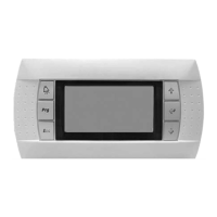
Details on the alphanumeric terminal, its keys, and status display.
Lists operating statuses and the user interface menu organization.
Explains terminal keys and introduces the touchscreen terminal.
Details unit status, modes, and menu bar navigation.
Outlines the touchscreen menu hierarchy and access levels.
Explains how to use the touchscreen terminal and access parameters.
How to search parameters, view synoptic, and manage access levels.
Procedures for password entry and viewing parameter curves.
How to start, stop, and manage unit operating modes.
Configuration of temperature and flow rate setpoints.
Function and operation of the safety and isolation damper.
Operation of mixing damper and filter monitoring.
Details on temperature control modes and setpoints.
Parameters for heating PID and supply air temperature limitation.
Adjusting supply air temp and controlling intake/exhaust fans.
Duct pressure control, setpoints, and flow rate fault detection.
Operation and defrosting of heat recovery units.
Details of coils, frost protection, and pump control.
Operation and conditions for free cooling and night cooling modes.
Air quality control and fire detection functions.
Installation and use of the Th-Tune room thermostat.
Displays for unit status and setpoint adjustment based on outdoor temp.
Limiting fresh air flow rate based on outdoor temperature.
Setting time and programming unit operation by schedule.
Schedule priority rules and access level descriptions.
Need for addressing terminals and controllers for communication.
Procedure for connecting a single terminal to a controller.
Electrical connections for controllers and remote screens on the pLAN.
Rules for addressing controllers and terminals on the pLAN network.
Procedures for changing terminal and controller addresses.
Configuring terminals as private or shared.
Verifying pLAN addresses and switching between networked controllers.
Supported protocols and Modbus RTU configuration.
Initializing and configuring Modbus TCP/IP and BACnet IP boards.
Setting IP addresses and subnet masks for network connection.
Accessing the web server and configuring pCO Com settings.
Settings for BACnet IP and requirements for LON setup.
Steps for configuring a LON network using configuration tools.
Naming and describing node models in LON configuration tools.
Requirements and configuration for KNX communication.
Steps for KNX configuration and available datapoint types.
Configuring and addressing KNX datapoints.
Pre-commissioning checks for wiring and circuits.
How to access and use test mode for PLC outputs.
Classification of faults and information on fault summary relays.
Fault memory storage and a list of detected faults.
Troubleshooting guide for various fault conditions.
Detailed diagnostics and solutions for specific faults.
User access levels and list of machine configuration parameters.
Machine parameters and parameters for setting unit configuration.
Additional setting parameters for fan and pressure control.
More setting parameters covering cooling, heating, and compensation.
Setting parameters for air quality, night cooling, and temperature compensation.
Setting parameters for temperature compensation, downgraded air flow, and fire safety.
List of parameters for reading operational values.
Reading parameters for heat recovery, electric heaters, and pumps.
Reading parameters for external generator, heat recovery, and programming requests.
Information on versions and setting fault levels.
Configuration of communication protocols for BMS1 and BMS2.
Procedures for calibrating sensors.
Configuration of input/output directions for software functions.
Setting priorities for unit operations like cooling and heating.
Parameters for intake and exhaust EC motor speed control.
| Brand | CIAT |
|---|---|
| Model | FLOWAY CLASSIC RHE |
| Category | Air Handlers |
| Language | English |