Do you have a question about the CIAT FLOWAY ACCESS and is the answer not in the manual?
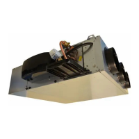
Overview of the PLC's role in controlling the air handling unit's components.
Description of the PLC's analog and on/off inputs and outputs with connector details.
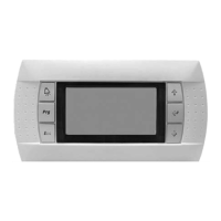
Information on the HMI terminal for unit operation, parameter modification, and status viewing.
Details on the 4.3-inch touchscreen terminal for unit operation and status monitoring.
Instructions on how to operate the touchscreen terminal for unit startup, shutdown, and parameter access.
Explanation of how to access different operational levels using passwords on the terminal.
Information on viewing and configuring parameter trend curves displayed on the terminal.
How to control the unit's start-up, shutdown, and remote operation modes.
Procedures for managing intake and exhaust filters, including fault detection for clogging.
Explanation of temperature control modes, setpoints, and PID parameters for heating and cooling.
Details on controlling intake and exhaust EC fans for constant flow rate or duct pressure.
Explanation of the fixed-speed wheel energy recovery unit's operation and conditions.
Description of the unit's coil options (hydraulic, direct expansion, electric) and their configurations.
Explanation of the free cooling mode, its conditions, and operational parameters.
How the unit uses night cooling to cool the building with colder night air.
Functionality for monitoring and controlling indoor air quality based on CO2 sensor readings.
Parameters and modes for fire detection and the unit's response to fire safety events.
How to use the Th-Tune room thermostat for remote control and status monitoring.
Function to adjust temperature setpoints based on outdoor temperature using compensation curves.
Limiting fresh air flow rate based on low outdoor temperatures to optimize operation.
Setting and management of date, time, and fault occurrence times using PLC parameters.
Programming the unit's operating modes (e.g., setpoints, frost protection) based on weekly and annual schedules.
Description of the three access levels (customer, installer, manufacturer) for parameter modification.
Procedure for addressing a single controller and terminal for basic network setup.
Connecting multiple controllers and terminals for expanded network capabilities.
Details on the physical wiring and cable requirements for the pLAN network.
Procedures for assigning unique addresses to controllers and terminals on the pLAN.
Steps to change the address of an HMI terminal connected to a controller.
Methods for changing the physical address of a controller on the pLAN network.
Configuring HMI terminals as private or shared for network access.
How to display and verify network addresses to diagnose connection issues.
Switching between controllers on a network using a shared HMI terminal.
Steps to configure the energy meter's address, speed, and parity settings.
List and description of parameters related to the energy meter's readings and status.
Configuration details for connecting the unit to a CMS using the Modbus RTU protocol.
Setup for Modbus TCP/IP and BACnet IP communication, including network configuration.
Guidelines for connecting and configuring the unit using the LON communication protocol.
Instructions for connecting and configuring the unit using the KNX communication protocol.
Essential checks on electrical cabling and hydraulic circuits before system start-up.
Procedure for addressing EC motors on the network, including factory settings and modifications.
How to use test mode to individually test PLC outputs without fault management.
Process for calibrating pressure and temperature sensors to correct offsets.
Distinction between maintenance and danger faults and their impact on unit operation.
Description of the fault summary relay and its triggering conditions.
How the PLC stores and logs the last 100 faults with date and time.
A comprehensive list of identified faults and warnings with their corresponding numbers.
Parameters related to unit model, sensors, fire detection, and damper configuration.
Parameters for language, date/time, ventilation control, and fan management settings.
Configuration settings for communication protocols like Modbus, LON, KNX, and BACnet.
Process for calibrating pressure and temperature sensors to correct offsets.
Configuration of input and output signal directions for various unit functions.
Parameters related to intake and exhaust fan motor settings, information, and configuration.
Parameters and readings associated with the unit's energy meter.
| Brand | CIAT |
|---|---|
| Model | FLOWAY ACCESS |
| Category | Air Handlers |
| Language | English |