3.6 - Display Fan Control
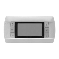
The controller runs the plug fans with an EC motor. The unit has one intake fan and one exhaust fan. Pressure sensors for measuring
the air ow are wired, on the EC motor or on the PLC (depending on the parameter P01 Unit model).
It is possible to control the intake air ow rate by constant ow rate or constant duct pressure.
Constant air ow control (P104)
The ow rate setpoints can be congured: Air intake ow rate setpoints 1 / 2 (P112, P113) and Air extraction ow rate setpoints 1
/2 (P128, P129)
The PID for the intake motor control is managed via P114 to P116, and the exhaust motor control via P130 to P132
Intake ow
112 Air intake fan ow rate setpoint 1
113 Air intake fan ow rate setpoint 2
114 Air intake fan ow control PID proportional band (P)
115 Air intake fan ow rate control PID integral time (I)
116 Air intake fan ow rate control PID derivative time (D)
Extraction ow
128 Air extraction fan ow rate setpoint 1
129 Air extraction fan ow rate setpoint 2
130 Air extraction fan ow rate control PID proportional band (P)
131 Air extraction fan ow rate control PID integral time (I)
132 Air extraction fan ow rate control PID derivative time (D)
Constant duct pressure control (P104)
In this case, a pressure sensor must be added and installed in the supply air duct. This sensor must be connected to the main
PLC.
The intake pressure setpoints are settable: setpoints 1/2 (P118, P119) The PID for the Intake motors control is managed via P120
to P122
In this case the exhaust fan operates based on intake ow rate feedback (default setting) with a multiplier factor (P106) to create
a positive pressure or vacuum pressure at the exhaust
A limiter function prevents the ow rate from exceeding a maximum value of + 10%. This function limits the maximum intake fans
percentage, according to the air ow rate.
Duct pressure
118 Air intake duct pressure setpoint 1
119 Air intake duct pressure setpoint 2
120 Air intake duct pressure control PID proportional band (P)
121 Air intake duct pressure control PID integral time (I)
122 Air intake duct pressure control PID derivative time (D)
124 Duct pressure low limit threshold
125 Duct pressure upper limit threshold
Motor
The motors are run via modbus. They must be addressed, and parameters P51 and P78 indicate whether their Modbus addresses
have been congured (see Commissioning chapter).
Conguration
51 Air intake FMA1 conguration
71 Air extraction FMA1 conguration
Motors warning
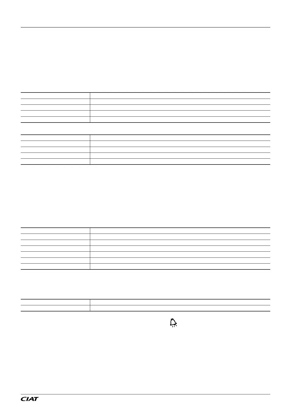
The motor warnings are fed back via the EC motors ModBus connection. The
button on the user interface is used to show and
display their presence. The parameters indicating whether or not a warning is present and displaying the last warning received are
shown in the EC motors information menu. The acknowledgement of a motor warning depends directly on the information fed back
via the ModBus connection.
These can be dened:
- as "maintenance" or "danger" type warnings via parameters P650 and P651.
- as taken into account (or not) on the fault output via parameter P292.
- as present (or not) on the CMS via parameter P293.
The motor warnings are stored in the fault memory of the PLC. In the "4.Fault memory" menu, the text states if the warning concerns
the intake motor or the exhaust motor and a warning code is also shown (see correlation table below). If several warnings are fed
back simultaneously, up to 4 fault codes may be shown with the text.
3 - FEATURES
EN-17 FLOWAY ACCESS