During the ventilation start-up phase, it operates.
• If there is a free cooling or night cooling requirement, the recovery unit is shut down.
• There is a 1°C hysteresis between start-up/shutdown
Wheel seizing prevention
The PLC gives the order for the wheel to operate 1 minute every 4 hours.
Load shedding of the wheel
Load shedding of the wheel is possible using parameter P158.
225 Temperature dierence for recovery unit run authorisation
Temperature
Return air < fresh air –P225 Return air > fresh air + P225
Heat recovery unit requirement
Cooling > 50% with a 50% hysteresis On Off
None Off Off
Heating > 50% with a 50% hysteresis Off On
Free cooling Night cooling Off Off
3.8 - Coil
The unit may contain a hydraulic or direct expansion coil, or an electrical heater.
This coil is congured using parameters P28 and P32.
The hydraulic coil may be a cooling coil, heating coil or mixed coil (heating or cooling according to the network temperature),
a direct expansion coil or electrical heater
28 Coil
32 Electric heater
3.8.1 - Mixed coil scenario
In the case of a mixed coil, the changeover may be made either via an on/o input or via the CMS (settable via parameter P162).
The changeover thermostat must be tted by the installer on the mixed coil inlet, at a point where water is in constant circulation.
The changeover status (heating or cooling made) can be viewed via parameter P345.
162 Changeover selection
3.8.2 - Frost protection
The hydraulic coil frost protected by controlling the unit's supply air temperature. If this is below the threshold P248, the frost
protection fault is triggered and the isolation register is closed, the ventilation stops and the coil valves are opened 100%.
A frost prevention function is available once the unit is shut down (via the HMI, the CMS or a danger fault), or during the ventilation
start-up phase. It consists in leaving the hydraulic coil valve slightly open (settable value) to maintain water circulation (P260). This
opening is maintained constantly (including when the machine is shut down).
248 Hydraulic coil frost protection safety threshold
260 Coil valve opening percentage when shut down
3.8.3 - Electrical heater scenario
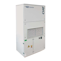
The control can operate an electrical heater comprising 2 on/o stages. These are operated in 3 stages (stage 1, followed by stage
2 and then stages 1 and 2).
Electric heating requirement
Stage 1
Stage 2
Stage 1+2
0 % 100 %
33 % 66 %
A minimum air ow rate is required to use the electric heaters (P126). If the ow rate is less than this parameter, the electrical
heater will not be able to start up and a "control limited" message will appear.
Electric heater conguration
32 Electric heater
126 Minimum ow rate for electrical heater operation
3 - FEATURES
EN-19 FLOWAY ACCESS