4.4.4 - Assigning private and shared HMI terminals
At this point, it is necessary to modify the list of terminals linked to each controller; to do so, follow the procedure below:
• enter conguration mode using the
and keys as described in the previous paragraph;
• press
until the cursor moves to the (I/O board address) eld;
• using the
keys, select the desired address for the controller. The only values selectable will be those of the controllers
that are on the network. If the pLAN network is not working correctly or if no controllers are present, the eld cannot be changed
and will display a “—”;
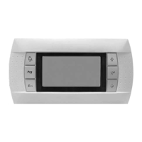
• pressing the
key again will bring up the mask sequences here on the right
• as above, press the
key to move the cursor from eld to eld. Press the keys to change the value of the current eld.
The P:xx eld shows the address of the selected controller. In the example above, controller No. 12 is selected;
In the case of a shared display for a set of units (maximum 31), the terminal must be congured on each unit in "Sh" mode.
The elds in the “Adr” column contain the addresses of the terminals associated with the controller whose address is 12; the
“Priv/Shared” column shows the terminal type.
• Shared = Sh= means that this terminal 02 may also be used with the other controllers present on the loop (shared
terminal)
• Priv = Pr= means that this terminal 03 can only operate with this controller no.12 (private terminal)
• to exit the conguration procedure and store the data, select "YES" in response to “OK?” and conrm with the
key
If the terminal remains inactive (no buttons pressed) for more than 30 seconds, it will automatically exit conguration mode
without saving any changes made.
4.4.5 - Checking the pLAN address
The pLAN address is displayed at the top of the main screen, in the centre. It is also possible to access parameter P720 in the
conguration parameters so that the controller address on the pLAN can be read.
When the system starts up, the pLAN may encounter a number of problems (board fault and terminal start-up) caused by incorrect
connections or if an incorrect address has been assigned. The state of the pLAN can be displayed in real time on a special mask
in order to identify which devices (controller or terminal) are correctly connected and addressed.
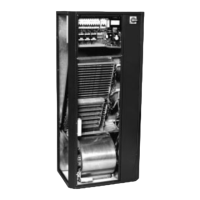
To display the special page, press
and simultaneously on any network terminal for at least 10 s. After the rst 5 seconds, a
page is displayed; after 5 more seconds, the following page appears:
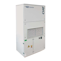
Controllers
Terminals
Once on the screen, network addresses 1 to 32 are displayed. The small rectangles represent the terminals and the large rectangles
, the controllers. If symbols appear then disappear, the pLAN may be unstable or, more likely, two components share the same
address. The number after Term indicates the address of the terminal used. The example shows that the network is made up of 3
controllers with the addresses 1, 2, 25 and 4 terminals with the addresses 3, 4, 15 and 26. Once the page has been veried, turn
o the power, check the connections and addresses, then power the system back on.
4 - MANAGING A NETWORK OF CONTROLLERS AND HMI TERMINALS
EN-31 FLOWAY ACCESS