EN-6
EN
Dual pump
Qty. 202 203 204 205 206 207 208 209 210 212 217 218 219
For models from 702V to 1100V x x x x x x x
For models from 1200V to 1800V x x x x x x x x
Power kW 3 4 4 5,5 5,5 7,5 7,5 11 11 15 2,2 4 7,5
Maximum nominal current A 6,3 8,0 8,0 10,3 10,3 13,8 13,8 20,0 20,0 26,5 4,5 7,8 13,8
● The cable routing must be made according to good working
practice, using cable glands.
Hydraulic connection
● Blanking plugs are used to guarantee that the inside of pipes
remain clean. Only remove them just before connecting the
piping.
● Start connecting in accordance with the direction shown by
the arrows on the inlet and outlet pipes.
● If welded connections are used, take appropriate precautions
to ensure that welding residues do not enter the circuit.
● Never introduce foreign bodies into the circuit.
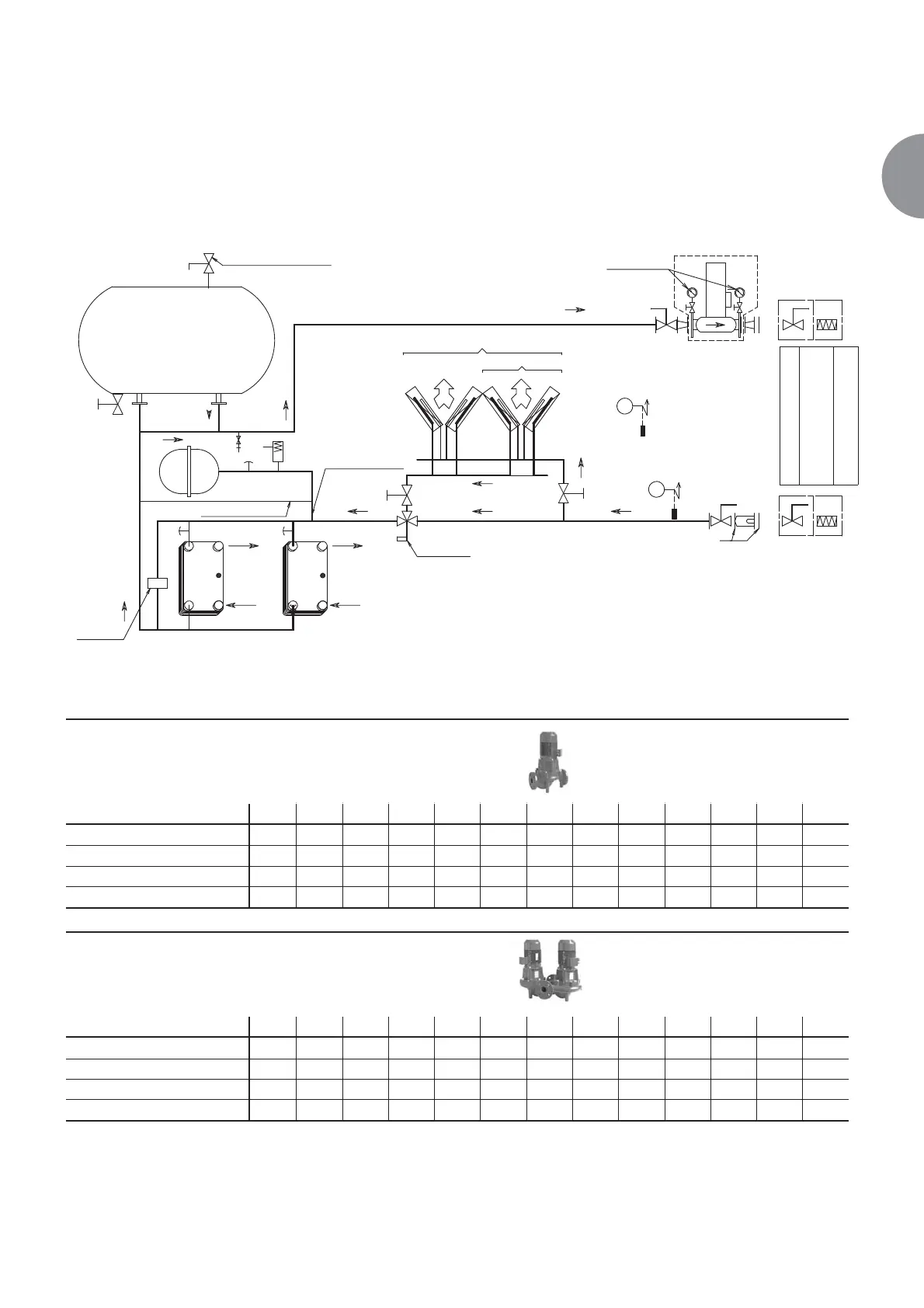
Hydraulic diagram
Hydraulic pumps (C and H versions)
1/2” air bleed valve
1/2” water
drainage valve
Flow rate
controller
Drain valve
automatic
Size: 1200 - 1800
Manual
bleed
valve
Manual
bleed
valve
Safety
valve
Size: 702-1100
Size: 1200-1800
Size: 702-1800
Pressure gauges +
shut-off valves option
Outdoor sensor
Water inlet sensor
Screen filter
Size: 702-1100 Flange: DN100
Size: 1200-1800 Flange: DN 125
B1
B2
AIR AIR
SUCTION
EXPANSION
SUCTION
EXPANSION
LDC version
F5
Expansion
vessel
WATER
WATER
WATER WATER WATER
WATER
3-way
valve
WATER
BUFFER TANK
500 Litres
LDH
Customer connections
Shut-off valves + press.
gauge kit
Flexible sleeve kit
Single pump
Qty. 102 103 104 105 106 107 108 109 110 112 117 118 119
For models from 702V to 1100V x x x x x x x
For models from 1200V to 1800V x x x x x x x x
Power kW 3 4 4 5,5 5,5 7,5 7,5 11 11 15 2,2 4 7,5
Maximum nominal current A 6,3 8,0 8,0 10,3 10,3 13,8 13,8 20,0 20,0 26,5 4,5 7,8 13,8