technological solutions
TECHNICAL DATA SHEET
Cav. Uff. Giacomo Cimberio S.p.A.
3
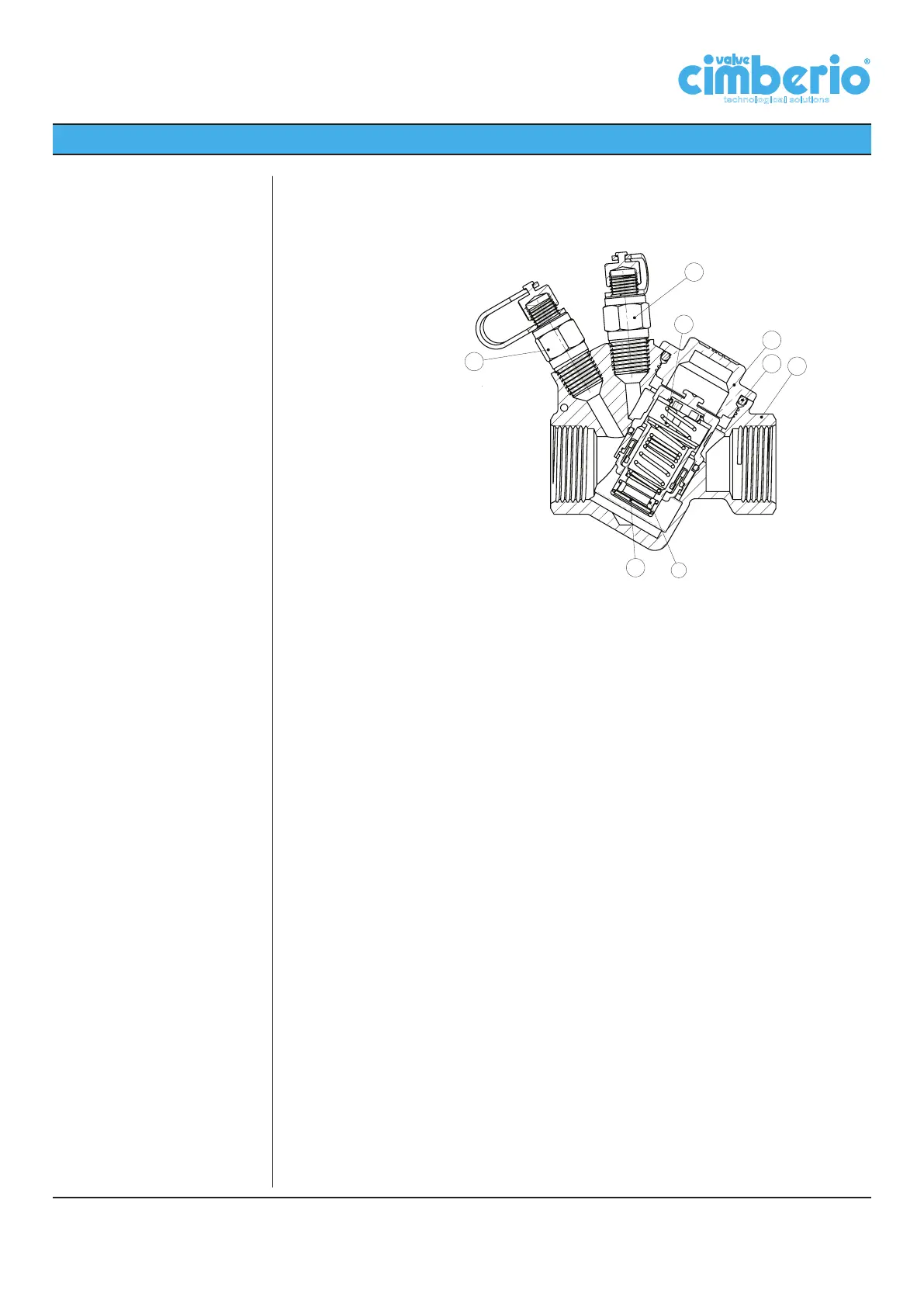
Cross section:
8
7
6
5
1
2
3
4
1. Valve body
2. Cartridge
3. Orifice
4. Elastic ring
5. O-ring
6. Plug
7. Blue binder point
8. Red binder point
Installation procedure:
Before installation of Cim 790, check that inside the valve and the pipes there are no foreign
matters which might damage the tightness of the valve.
Burr pipe connections after having threaded them and distribute the sealing material on
pipe threads only and not on valve threads.
It is advisable to install a filter and an intercepting valve on the feed line.
Before installation of Cim 790, check that cartridge flow rate is properly matching the pro-
ject requirements and that pump is able to assure the minimum differential pressure (Δp
min) stated in the tables of following pages (section “Tables”).
Valves may be installed either on horizontal or vertical pipelines, following the arrow direc-
tion casted on the valve body, which shall be the same as the flow one.
For assembly purposes, use a spanner, not a pipe wrench, by applying necessary work-
ing torque only on the valve end nearest the pipe. This helps get a firmer grip and avoids
potential damages to valve body.
Make sure that pipe threading length is not longer than valve threads.
It is advisable to flush the installation before service. To this purpose, remove all cartridges
of the installed valves, following the instructions detailed in “Maintenance” part of the pre-
sent brochure.


 To Next Page
 Loading...