SERVICE
MANUAL
AND
PARTS LIST
CATALOG
FIGURE
14A
Quill
Feed
Torsion
Spring
winds.
Grip
the
tang
of
spring
(80B) with a
pliers
and
place
a
rag
over
spring
housing.
Pull
tang
of
spring
free
of
notch
in
spring
housing
(79B)
and,
at
the
same
time,
step
back
while
spring
unwinds.
The
tang
at
inner
end
of
spring
lies
in
groove
of
pinion
shaft
(78B).
This
spring
is
most
easily
replaced
by
two
men,
each
handling
spring
with
a
pair
of
pliers.
[Grease
spring
before replacing.]
Have
spindle
at
its
bottom
position,
fully
wind
spring,
back
off
one
notch
and
hook
spring
in
housing.
[This
spring
is
only
strong
enough
to
balance
weight
of
sleeve
assembly.
It
is
not
intended
to
return
spindle
to
its
upper
po
sition. ]
4.
Remove
three
screws
(87B),
lift
off
spring
housing
(79B)
and
pull
out
pinion
shaft
(78B).
Push
spindle
and
sleeve
(92B) up
far
enough
to
remove
stop
key
(69B)
and
lower
sleeve
assembly
out
of
head.
Stop
key
contacts
ad
justing
stop
block
(52B).
To
Remove
Drive Spindle
Assembly:
Style 1-B
(See Pages 32, 34.)
1.
Proceed
as
per
instructions
above
under
"To
Remove
V-Belt
Housing"
and
"To
Remove
Splined
Spindle
Sleeve."
2.
Unscrew
hub
retainer
(194B)
that
is
attached
to
spring
pin
(191B),
spring
(192B)
and
spring
retainer
screw
(193B).
Lift
off
handle
hub
(190B)
and
dial
(189B).
3.
Tape
a
small
rag
to
the
exposed
end
of
pinion
shaft
(183B)
to
protect
shaft
when
spring
un
winds.
Grip
the
tang
of
spring
(187B)
with
a
=
14
pliers
and
place
a
rag
over
spring
housing.
Pull
tang
of
spring
free
of
notch
in
spring
housing
(185B)
and,
at
the
same
time,
step
back
while
spring
unwinds.
The
tang
at
inner
end
of
-spring
lies
in
groove
of
pinion
shaft
(183B). [See
Figure
14A. ]
This
spring
is
most
easily
replaced
by
two
men,
each
handling
spring
with
a
pair
of
pliers.
[Grease
spring
before
replacing.]
Have
spindle
at
its
bottom
position,
fully
wind
spring,
back
off
one
notch
and
hook
spring
in
housing.
[This
spring
is
only
strong
enough
to
balance
weight
of
sleeve
assembly.
It
is
not
intended
to
return
spindle
to
its
upper
po
sition.
]
Drain
oil
from
spindle
housing
by
removing
plug (124B)
and
rotating
spindle
housing (15
IB)
to left. [See
Figure
16B.] Unscrew hand
clutch
knob (175B,
page
34)
and
remove
cover
plate
(123B,
page
32).
Loosen
lock
screw
(179B,page 34),
unscrew
clutch
adjusting
col
lar
(178B)
and
remove
male
friction
clutch
(181B)
[See Figure 15C], key (184B)and
spiral
gear
(182B). Loosen
clamp
screw
(205B).
Remove
two
set
screws
(163B, 162B,
page
32)
from
side
of
spindle
housing.
Replace
handle
hub (190B, page 34).
Rotate
handle (196B) to
raise
sleeve
(144B, page 32) and, by knocking
it
against
driven
gear
(115B),
force
worm
shaft
(118B)
up out of spindle housing. [See
Figure 15A.] Pull out pinion shaft (183B,
page
34).
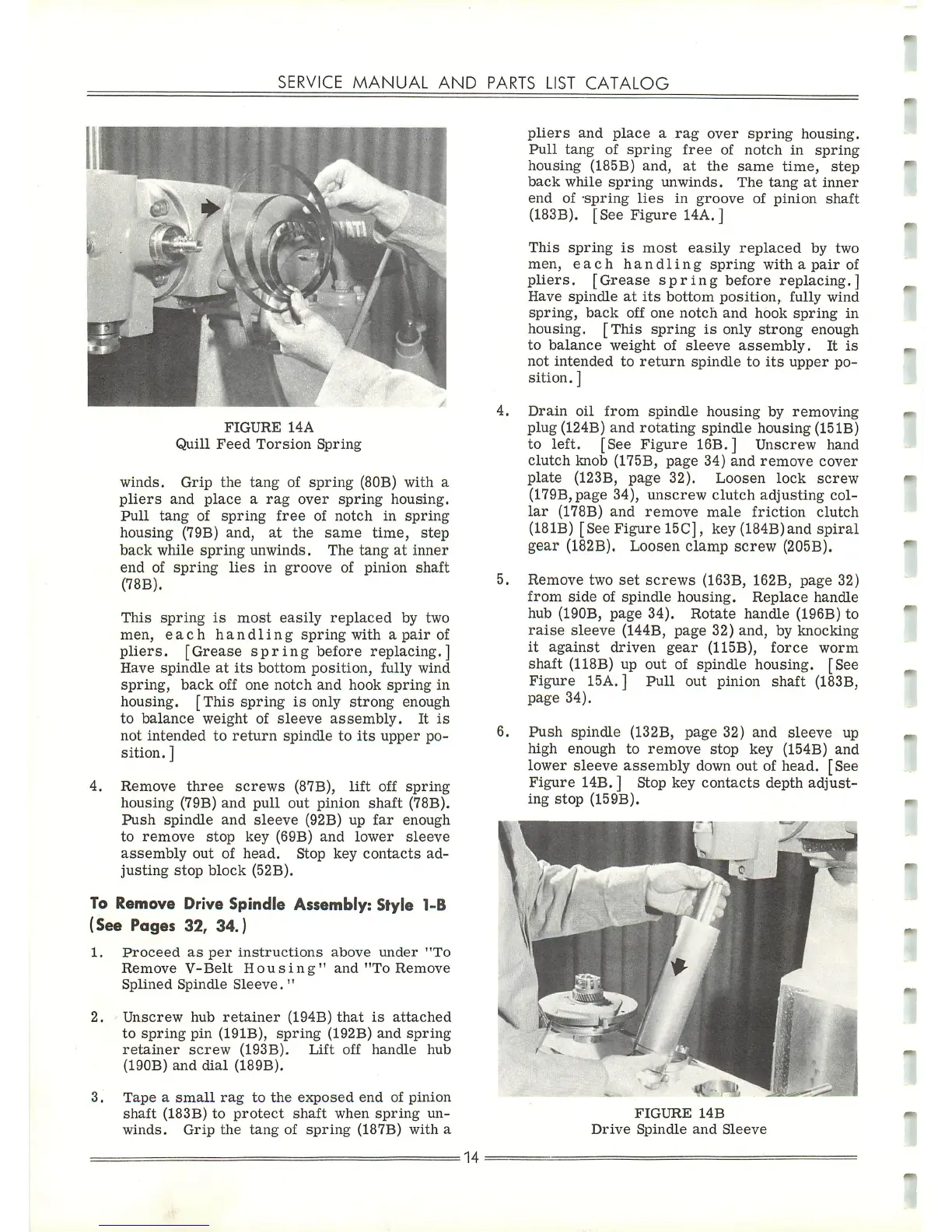
Push
spindle (132B,
page
32)
and
sleeve
up
high
enough
to
remove
stop
key
(154B)
and
lower sleeve
assembly
down out of head. [See
Figure
14B. ] Stop key contacts depth adjust
ing
stop
(159B).
FIGURE
14B
Drive
Spindle
and
Sleeve
 Loading...