-31-
33. Electronic ‘AND’ Gate
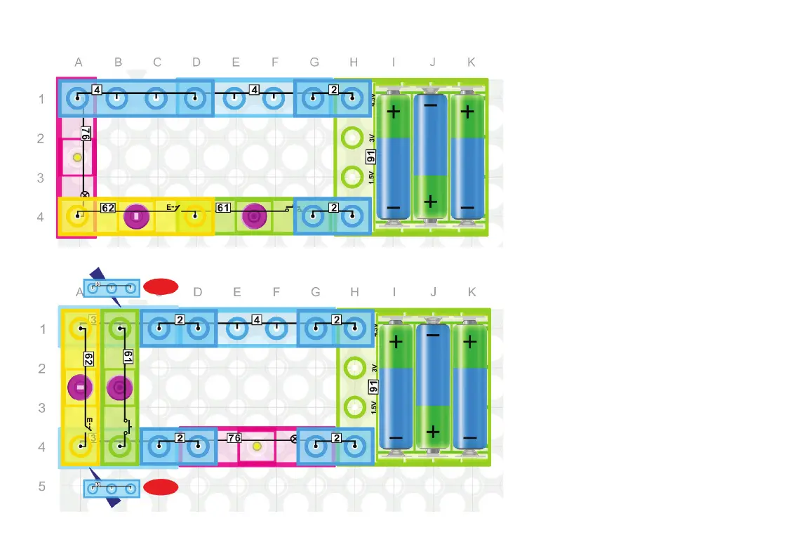
Build the circuit to the left. Note that the
lamp (76) only turns on when both the
switch (62) and press switch (61) are
ON. In digital electronics there are seven
logic gates: AND, OR, XOR, NOT, NAND,
NOR, and XNOR. This circuit represents
an AND gate. If ON = True and OFF =
False then an AND gate is best dened
as: The output is TRUE only when both
inputs are True. Therefore, the two inputs
represented by the press switch (61) and
the switch (62) must both be ON (TRUE)
in order for the output represented by the
lamp (76) to be ON (TRUE).
34. Electronic ‘OR’ Gate
Build the circuit to the left. This circuit
represents an OR gate. If ON = True and
OFF = False, then an OR gate is best
dened as: The output is TRUE when any
input is True and False only when all the
inputs are False. In this circuit the output
represented by the lamp (76) is ON (True)
if either input represented by the press
switch (61) or the switch (62) or both is
ON (TRUE). The lamp (76) is OFF (False)
only when both switches are OFF (False).
1st level
1st level



 To Next Page