Hardware Specifications and Cable Pinouts C-13
Cable Pinouts
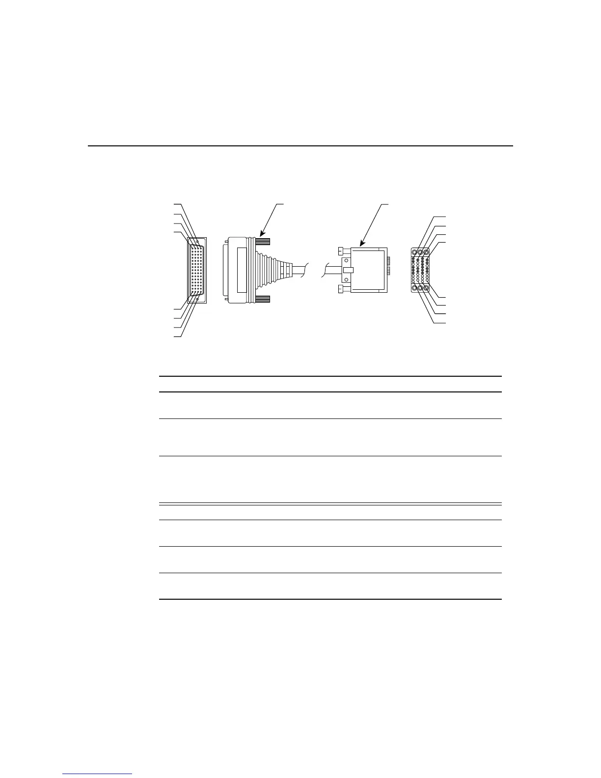
Figure C-5 V.35 Cable Assembly
Table C-11 V.35 Cable Pinouts (DB-60 to 34-Pin)
60 Pin
1
Signal Description Direction 34 Pin Signal
J1-49
J1-48
MODE_1
GND
Shorting group – – –
J1-50
J1-51
J1-52
MODE_0
GND
MODE_DCE
Shorting group – – –
J1-53
J1-54
J1-55
J1-56
TxC/NIL
RxC_TxCE
RxD/TxD
GND
Shorting group – – –
J1-46 Shield_GND Single – J2-A Frame GND
J1-45
Shield
Circuit_GND
–
Twisted pair no. 12 –
–
J2-B
Shield
Circuit GND
–
J1-42
Shield
RTS/CTS
–
Twisted pair no. 9 —>
–
J2-C
Shield
RTS
–
J1-35
Shield
CTS/RTS
–
Twisted pair no. 8 <—
–
J2-D
Shield
CTS
–
H1975
-46
-45
-16
-15
1-1
-30
-31
-60
Connectors are not to scale.
60-pin connector (J1)
34-pin connector (J2)
J2-B
J2-D
J2-A
J2-C
J2-KK
J2-MM
J2-LL
J2-NN