18 Upgrading Cisco 4500, Cisco 4500-M, Cisco 4700, and Cisco 4700-M Memory
Memory Replacement Procedures
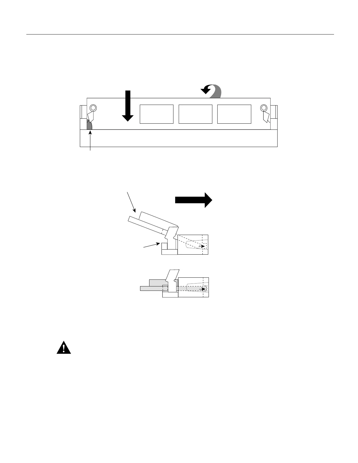
Figure 13 Inserting Shared Memory SIMMs
Step 7
To insert a SIMM, angle it into position, then carefully push down and back on the edges,
holding each edge so that it snaps securely in place. (See Figure 13.) When it snaps into
place, the two metal clips fit over the edge of the SIMM and hold the SIMM horizontally.
Caution Avoid damaging the SIMMs and SIMM socket by handling them roughly. The SIMMs are
also sensitive to ESD damage.
Step 8 Check that the SIMM is straight and that the holes are aligned with the socket guide posts.
(See Figure 13.)
If you have completed all SIMM replacement procedures, proceed to the section “Replacing
Network Processor Modules” on page 22.
Polarization notch
Push the SIMM down and back
The socket guide posts
insert through the SIMM holes
(on both sides)
Push the SIMM down and back
Side view, SIMM inserted
Top view
H1052a

 Loading...


