20 Upgrading Cisco 4500, Cisco 4500-M, Cisco 4700, and Cisco 4700-M Memory
Memory Replacement Procedures
Caution Handle SIMMs by the edges only. SIMMs are ESD-sensitive components and can be
damaged by mishandling.
Step 2 Hold the SIMM with the polarization notch on the right and the component side away from
you with the connector edge at the bottom.
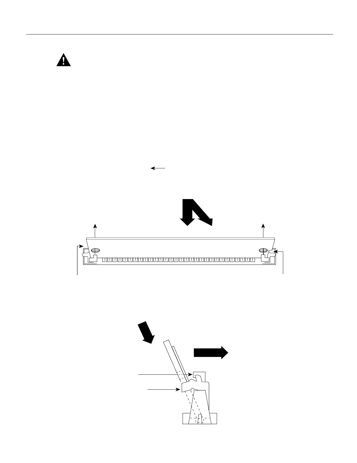
Step 3 Referring to Figure 15, insert the Flash memory SIMM at a 45-degree angle and rock it into
its vertical position. (See Figure 8 on page 12.) When the SIMM is properly seated, the
socket guide posts will insert through the alignment holes, and the locking springs will
click into place. Use the minimum amount of force required.
Figure 15 Inserting Flash Memory SIMMs
The socket guide posts insert
through the SIMM holes
(on both sides).
3.
The locking spring will
clip the front side of the SIMM
when it is fully installed
(on both sides).
4.
H2474
Polarization
notch
1. Insert the SIMM into the socket at an angle 45° from vertical.
The socket guide posts insert
through the SIMM holes
(on both sides).
3.
The locking spring will
clip the front side of the SIMM
when it is fully installed
(on both sides).
4.
Side view
2. Push the SIMM down and back.
2. Push the SIMM down and back.
1. Insert the SIMM into the socket at an angle 45° from vertical.
Top view
Front of the chassis

 Loading...


